Clamping assembly for high-voltage solid state devices

a technology of high-voltage solid-state devices and clamping parts, which is applied in the direction of electrical apparatus construction details, electrical apparatus casings/cabinets/drawers, electrical apparatus contruction details, etc., can solve the problems of not being particularly effective in conducting electricity, not being well suited for use as electrical insulators, and being particularly useful for electrical conduction. , to achieve the effect of convenient ascertaining the magnitude of the compressive force and relatively uniform distribution of the clamping for

Inactive Publication Date: 2004-01-13
VARIAN MEDICAL SYSTEMS
View PDF7 Cites 27 Cited by
  • Summary
  • Abstract
  • Description
  • Claims
  • Application Information

AI Technical Summary

Benefits of technology

The present invention has been developed in response to the current state of the art, and in particular in response to these and other problems and needs that have not been fully or adequately solved by currently available clamping assemblies. Thus, it is an overall object of embodiments of the present invention to provide a clamping assembly that facilitates relatively uniform distribution of the clamping force across the top of the stack notwithstanding any misalignment of the stack, and that facilitates ready ascertainment of the magnitude of the compressive force being applied. Embodiments of the present invention are especially well suited for use in the context of high voltage solid state devices. However, it will be appreciated that various features and advantages of the present invention may find useful application in other environments as well.

Problems solved by technology

One characteristic of such materials however is that they are not particularly effective in conducting electricity, nor are they well suited for use as electrical insulators.
Because such materials are not particularly useful for electrical conduction, or for impeding electrical conduction, they are generally referred to as "semiconductors."
As discussed below, however, many known clamping devices suffer from a variety of shortcomings that render them ineffectual and / or cause damage to the stack elements.
Some of the problems and shortcomings with known clamping devices relate to the materials used to construct those devices.
In high voltage applications, in particular, the voltages involved are so large that the spacing between the stack and the compression bolts is insufficient to prevent arcing between the stack elements and the compression bolts.
A significant problem with the fiberglass compression bolts relates to the relative softness of the fiberglass material.
As a result of the high clamping forces that they are required to impose, the relatively soft threads of the fiberglass compression bolts are vulnerable to stripping.
A related problem with compression bolts constructed of fiberglass and like materials concerns the difficulty of tightening the nuts on the compression bolts in a symmetric fashion.
As discussed below, this result is difficult to achieve in practice, and it is generally the case that the nuts on the compression bolts are tightened at least somewhat asymmetrically.
A typical consequence of even slightly asymmetric or unbalanced tightening of the nuts on the compression bolts is that the magnitude of the mechanical stresses and strains between the nut and corresponding compression bolt in the region of relatively greater stack compression is materially higher than the magnitude of the mechanical stresses and strains between the nut and corresponding compression bolt in the region of relatively lesser stack compression.
The high stresses and strains that typically result from asymmetric tightening of the nuts on the compression bolts can cause stripping of the compression bolt threads, thereby requiring removal and replacement of the compression bolt.
In addition to the problems inherent in the use of compression bolts made of fiberglass or similar materials, known clamps and clamping devices suffer from other shortcomings as well.
One such problem relates to the magnitude of the clamping forces employed in compressing a particular stack of elements.
However, it is difficult, if not impossible, for the assembler of the solid state device to determine with any degree of certainty the magnitude of the clamping force being applied as the nuts on the compression bolts are tightened.
Thus, an assembler may inadvertently overtighten or undertighten the nuts on the compression bolts.
Specifically, where the nuts on compression bolts are overtightened, the resulting compressive force exerted on adjacent regions of the stack may become sufficiently large in magnitude as to cause damage to the stack elements.
In many cases, this damage will be imperceptible and may not be fully appreciated until attempts are made to energize and use the solid state device.
Alternatively, in the case of undertightening, if the compressive force exerted by the clamping assembly on the stack is of insufficient magnitude, the contact between the stack elements that is required for efficient operation of the solid state device will not be achieved.
Not only is it difficult, in the context of known clamps and clamping assemblies, to ascertain the magnitude of the compressive force being applied to the stack, but known clamps and clamping assembly typically make no provision for a reliable guide that would insure that the compressive force applied is uniformly distributed across the upper surface of the stack.
Such methods are unreliable, however, and typically result in an imbalance in the compressive force applied to the stack.
As a result, the compressive force applied by the clamping device is not uniformly applied across the top of the stack, and the compressive force is relatively greater in some regions of the stack than in others.
Such imbalances in the magnitude of the compressive force applied to the stack can cause crushing or other damage to stack elements in the region of the relatively higher compressive force and, at the same time, may result in insufficient contact between the stack elements in the region of the relatively lower compressive force.
Finally, known clamping devices and systems are generally ill-equipped to compensate for the horizontal misalignment of stack elements that commonly occurs.
Thus, even if the compression bolts are tightened uniformly, a force imbalance on the stack occurs because one side of the stack is higher than the other side of the stack.
As discussed elsewhere herein, such force imbalances materially compromise the operation and reliability of the solid state device.
Even in instances where horizontal misalignment of the stack elements could be readily perceived, known clamping devices provide no effective way to compensate for, or remedy, the misalignment.
While attempts could be made to overtighten the nuts of some compression bolts and undertighten others, so as to achieve application of a compressive force somewhat more evenly distributed across the top of the misaligned stack, such relative overtightening and undertightening implicates, as described earlier, a variety of undesirable effects with regard to the compression bolts, and the overall integrity and operation of the solid state device.

Method used


Image

  • Clamping assembly for high-voltage solid state devices
  • Clamping assembly for high-voltage solid state devices
  • Clamping assembly for high-voltage solid state devices

Examples


Embodiment Construction

Reference will now be made to figures wherein like structures will be provided with like reference designations. It is to be understood that the drawings are diagrammatic and schematic representations of various embodiments of the claimed invention, and are not to be construed as limiting the present claimed invention, nor are the drawings necessarily drawn to scale.

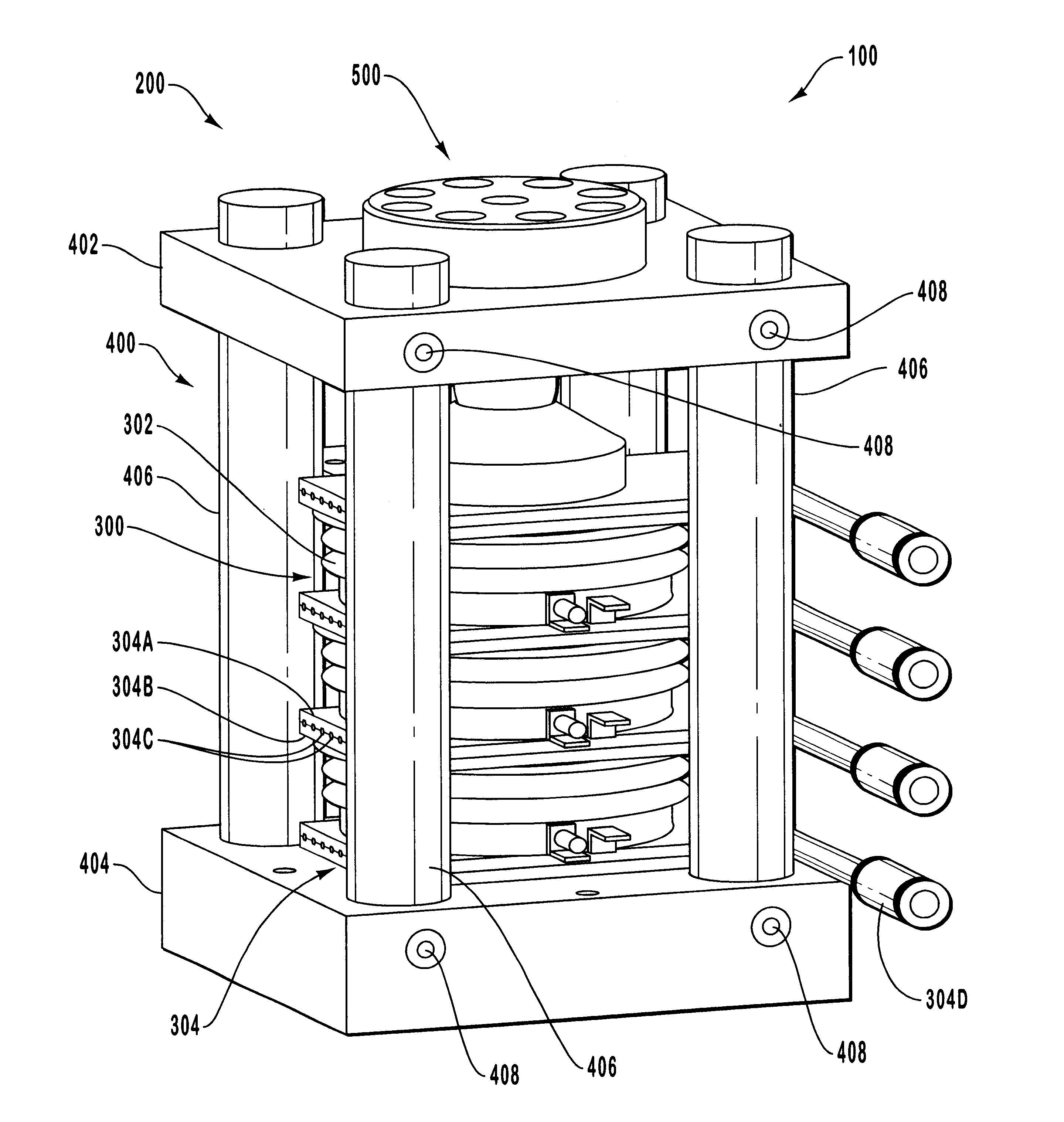
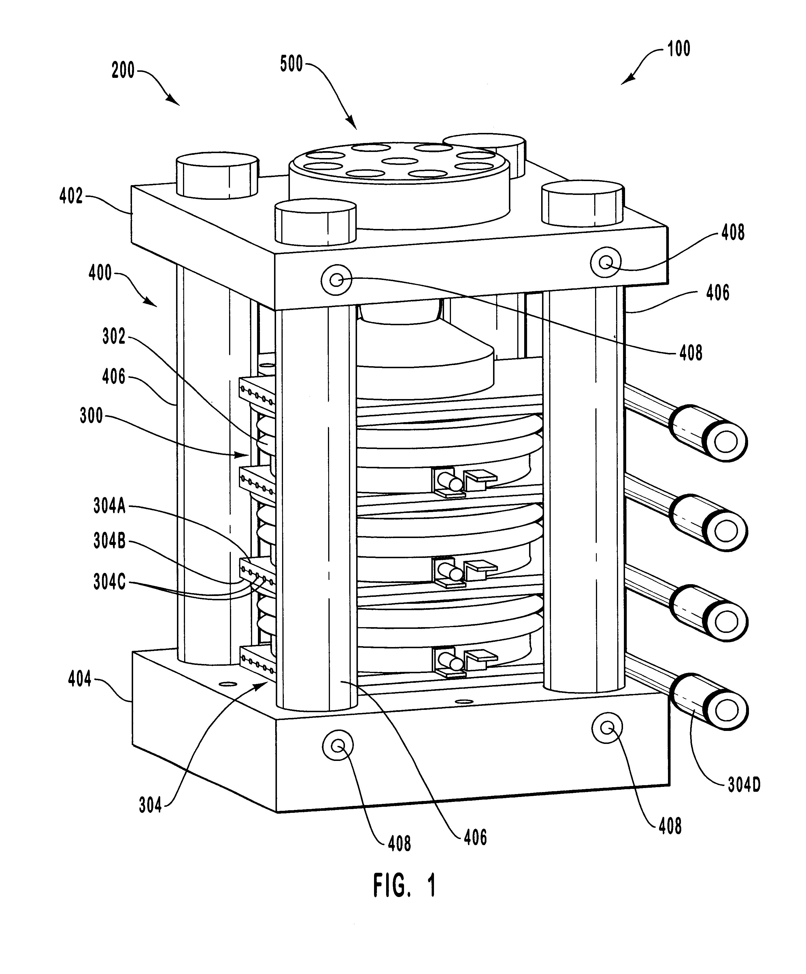
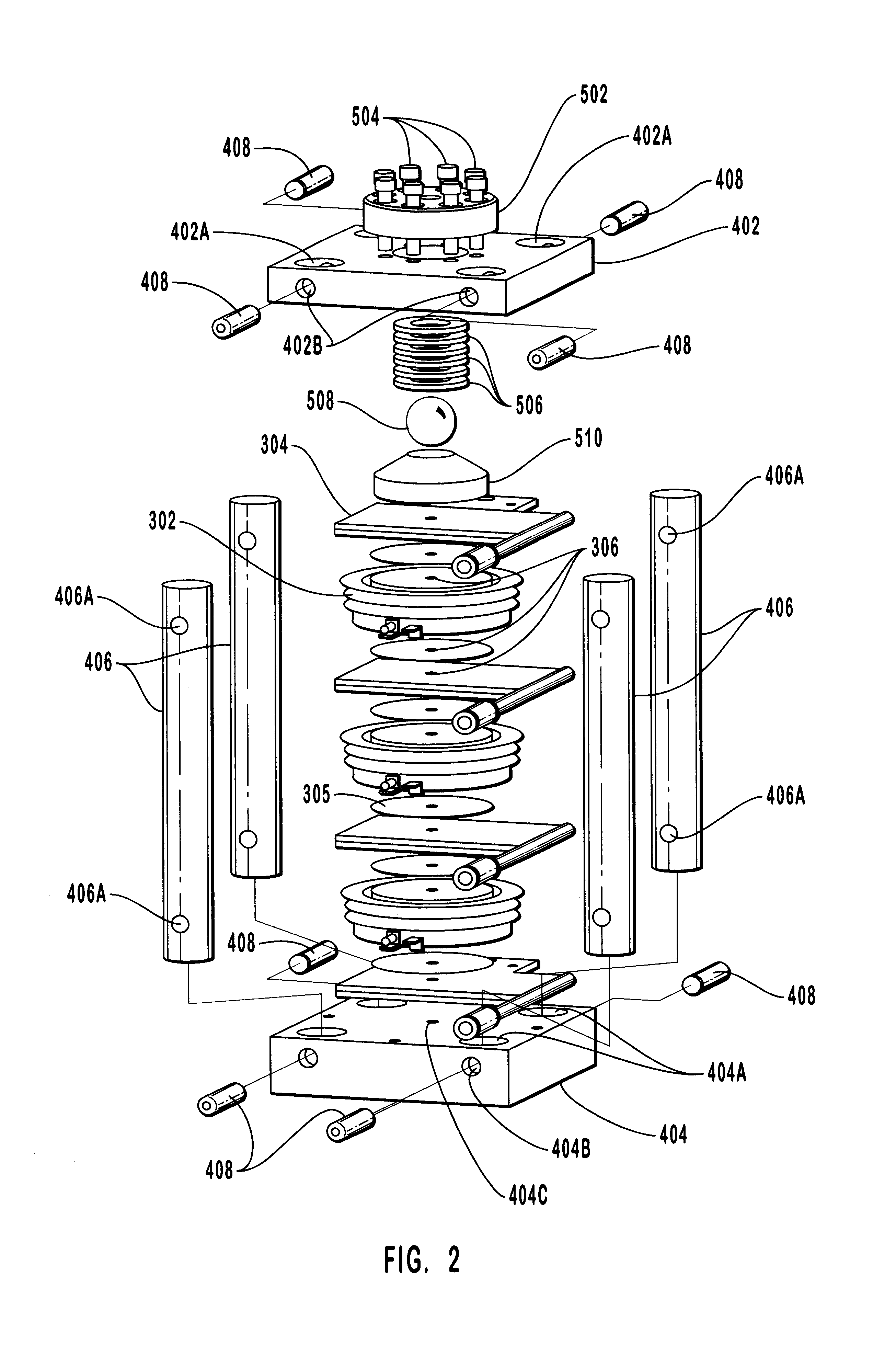
Reference is first made to FIG. 1, wherein a solid state assembly is indicated generally at 100. Solid state assembly 100 includes a clamping assembly 200 and a stack 300. In general, stack 300 is secured in clamping assembly 200 so that clamping, or compressive, forces exerted by clamping assembly 200 can be transmitted to stack 300.

Clamping assembly 200 includes clamp frame 400 and compression assembly 500 mounted in clamp frame 400 and positioned so as to facilitate imposition of compressive forces on stack 300. Clamp frame 400 includes upper clamping plate 402 and lower clamping plate 404 joined by a plurality of con...


PUM


Abstract

A clamping assembly for use in conjunction with high voltage solid state devices. The clamping assembly includes a clamp frame having upper and lower clamping plates substantially composed of aluminum and joined together by four dielectric rods composed of glass laminate material. The clamping assembly further includes a compression assembly mounted in the upper clamping plate and including several spring washers disposed in a recess defined by the upper clamping plate. The position of a compression cap attached to the upper clamping plate by eight cap screws can by adjusted by way of the cap screws so as to compress, or deflect, the spring washers. The spring washers in turn exert a compressive force that is a function of the spring constant k of the spring washers as well as of the distance over which the spring washers are compressed by the compression cap. The compressive force thus generated is transmitted to a pivot ball seated in a recess collectively defined by the spring washers. A force distribution member defines a socket in which the pivot ball is partially received and transmits the compressive force to a stack which is disposed between the upper and lower clamping plates and includes semiconductor devices and heat sinks. The socket in the force distribution member permits the force distribution member to rotate with respect to the pivot ball so that the compression surface of the force distribution member automatically moves to a position wherein the compression surface is in substantial contact with the upper surface of the stack, notwithstanding any horizontal misalignment of the stack. As a result of the substantial contact between the compression surface and the upper surface of the stack, the compressive force is distributed substantially uniformly across the upper surface of the stack.

Description

1. The Field of the InventionThe present invention relates generally to systems and devices for use in securing semiconductor elements of solid state devices. More particularly, embodiments of the present invention relate to a mechanical clamping assembly which facilitates uniform application of clamping forces to the semiconductor elements of high voltage solid state devices so as to ensure substantial thermal and electrical communication between the semiconductor elements, and thereby contribute to safe, reliable, and effective operation of the solid state device.2. The Relevant TechnologySemiconductor materials, and devices that employ them, have been in use for some time. The physical and chemical structure of semiconductors makes them especially well suited for use in a variety of applications. In particular, it is well known that some materials such as silicon and germanium are arranged into regular atomic patterns or structures, often referred to as crystals. One characterist...

Claims


Application Information

Patent Timeline
Patent Type & Authority Patents(United States)
IPC IPC(8): H01L23/473H01L23/34H01L23/48H01L25/11H01L25/10
CPCH01L23/473H01L25/117H01L24/72H01L2924/1301H01L2924/01002H01L2924/01005H01L2924/01012H01L2924/01013H01L2924/01015H01L2924/01025H01L2924/01029H01L2924/0103H01L2924/01032H01L2924/01033H01L2924/01039H01L2924/01049H01L2924/01051H01L2924/01058H01L2924/0106H01L2924/01075H01L2924/01023H01L2924/01024H01L2924/01087H01L2924/01006H01L2924/01019H01L2924/00
Inventor HITCHCOCK, ROGER N.
Owner VARIAN MEDICAL SYSTEMS
Why Eureka
Try Eureka