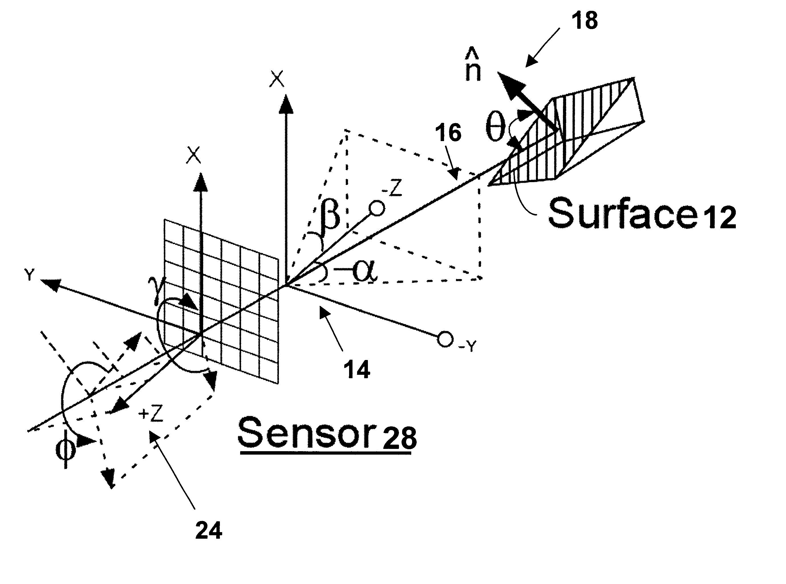
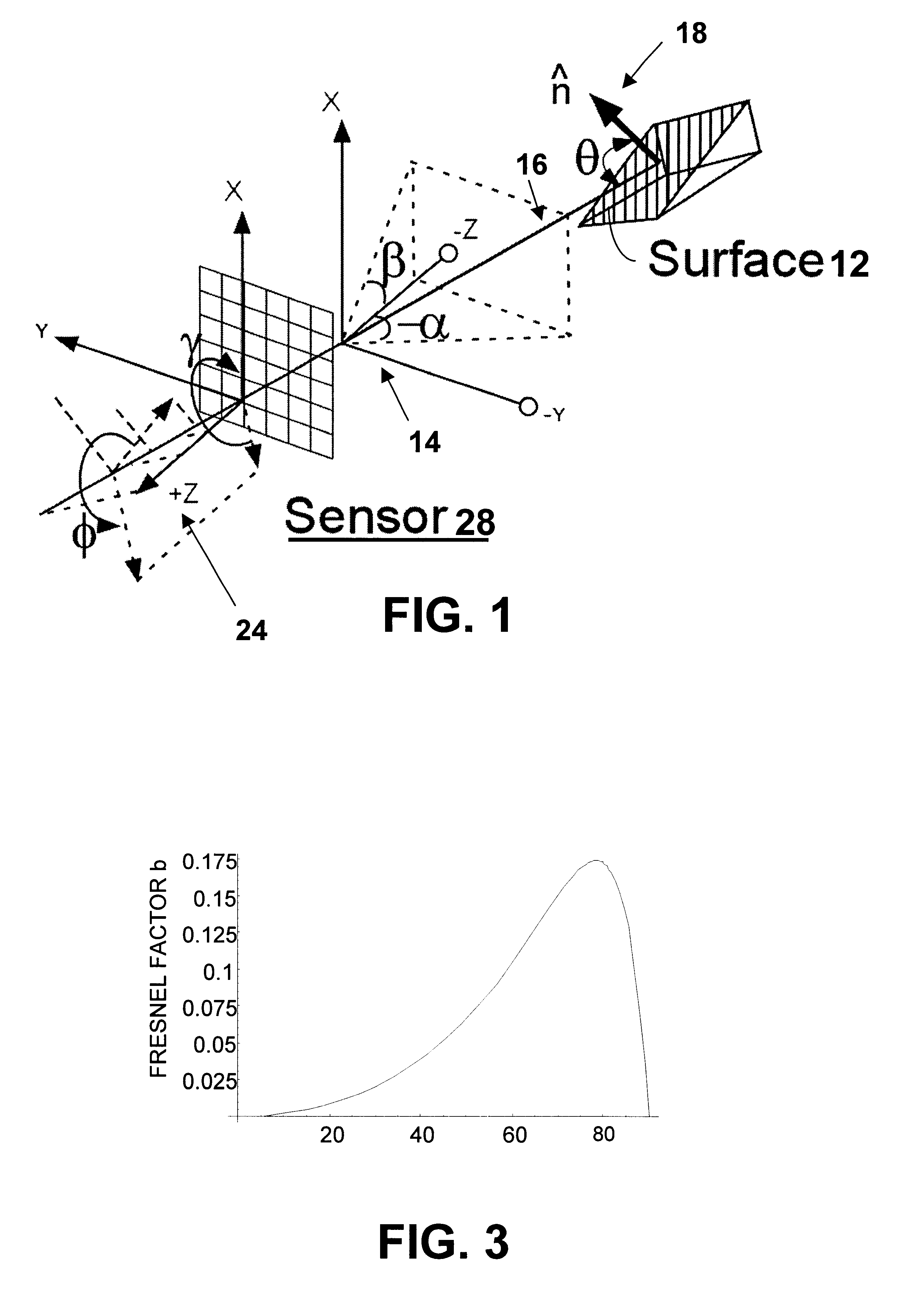
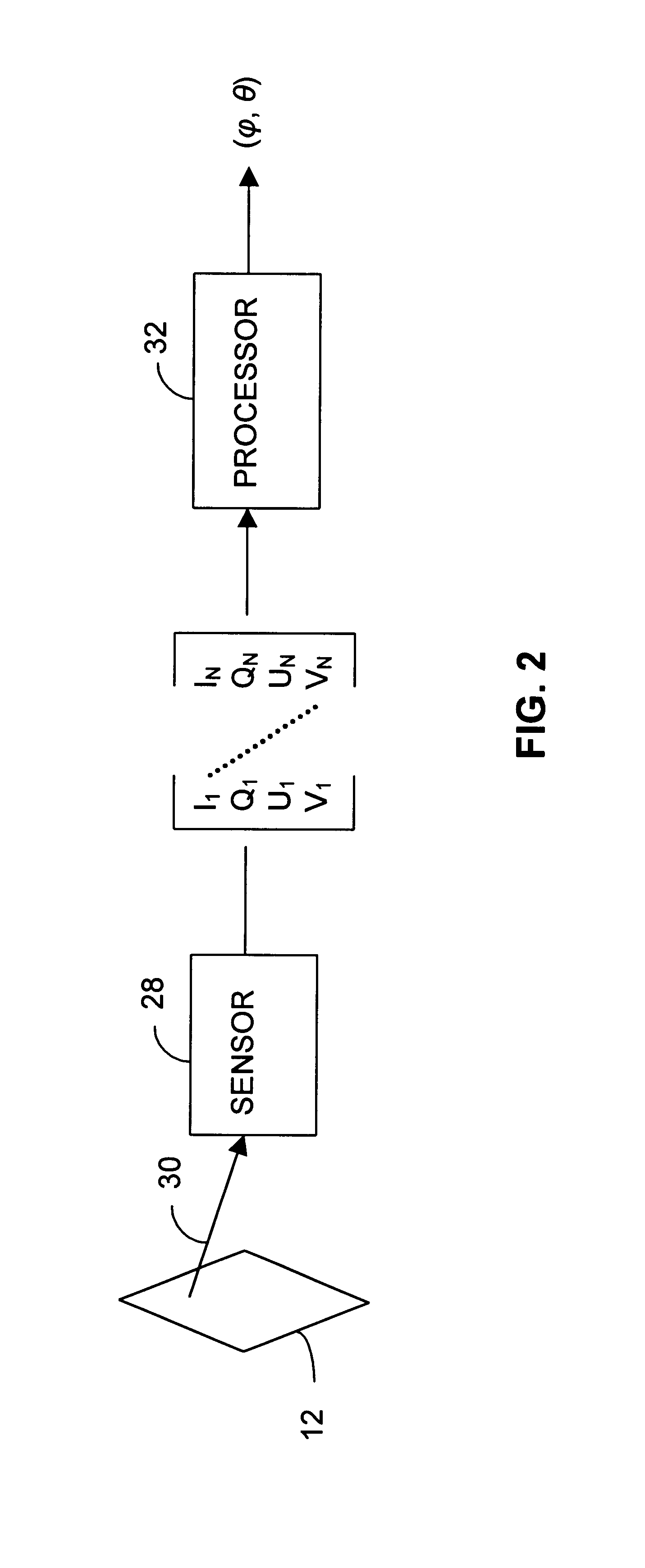
Some of the practical challenges involve control of, or accounting for, spatial non-uniformity of illumination or surface reflectance [Proll2000].
An implicit requirement is the arrangement for pre-measurement setup, so the approach typically cannot be used spontaneously.
Stereometric-disparity methods cannot be used for objects located outside the overlap in the tandem sensors' fields of view.
But shape-from-shading and shape-from-texture methods often suffer from ambiguities that typically confine them to ascertaining only relative (differential) rather than absolute surface orientation.
One way to overcome the
ambiguity is to employ variable-incidence
active illumination, but this limits flexibility and measurement spontaneity.
But closer investigation reveals that, without further refinement, such polarimetric imaging may itself be limited to ascertaining relative rather than absolute surface orientation.
So far, there has been no reasonably robust way to determine three-dimensional surface orientation by passive
polarimetry from a single vantage point.
Now, Equation (10) compares the number of known quantities in Equation (9) with its number of putatively unknown quantities, and the results make attempting such a computation appear ill-fated.
Nuisance variables are those unknown parameters that are of no particular application interest but nevertheless, because their values are unknown, interfere with the task of inferring the parameters of interest.
Unfortunately, as one may apprehend from Equations (9) and (10), such domain broadening disrupts the aforementioned methods for inferring angle .theta. and also prevents Equation (12) from serving as a way to obtain angle .phi..
The second major problem-causing factor is that the balance between emission and reflection is ambiguous.
This inability results from the fact that the balance between surface self-emission (Planck term L.sub..
lambda. regulated by unknown surface temperature) and incident environmental illumination I.sub.i,.
lambda. is not known.
Theoretically, the first of three approaches to be described below would suffice by itself, but practical limitations imposed by
noise and finite
measurement precision restrict certain approaches to respective regimes of applicability.
This assumption is not always valid, and whether it is valid in a particular case will rarely be known before the measurement is made.
As will later be shown, though, the fact that the measurements are taken in the spectral neighborhood of a
resonance often makes that foreknowledge unnecessary; the constrained behavior of the Fresnel reflectance factors in a resonance neighborhood permits their
inference from the spectral Stokes
radiance measurements.
The choice of the optimal set and number of features is the "
feature selection" problem.
Unfortunately, since Equation (15) is highly non-linear, standard determinations of singularities and intrinsic dimensionality, applicable to linear equations, cannot be applied.
This typically results from modeling infidelity or
creep-in nuisance variability.
This imposes a practical limit on NEd.theta. and NEd.phi. independently of the sensor
noise level or the number of features employed.
DoP causes a deterministic "
distortion" of the feature vectors.
This skewness draws the corresponding tangent vectors close to one another, rendering any
inference in this region highly susceptible to
noise.
The choice of the optimal set and number of features is the "
feature selection" problem.
Without using the tangent vectors or tuning them in that way, the unknown
distortion due to variable surface-incident DoP would increase the .theta.
inference error to well beyond 10.degree. across much of its range.
But this is not nearly as desirable as operating in the low-DoP, bimodal regime, which requires substantially less SNR and fewer spectral samples for well-conditioned inference
processing.
If it is, the measurements may have been then in a regime where they tend to be unreliable.
Some, though
observable in measurements, may simply not exhibit the "strength" necessary to manifest the characteristic features in the Fresnel reflectance factors at sufficient
signal-to-noise ratio.
As FIG. 19 illustrates, on the other hand, polycrystaline
silicon's resonance near 0.3 microns is not well suited to use in the Case 2 inference technique.
ns to rise. If that relationship does not prevail in the resonance's neighborhood, on the other hand, that resonance tends not to be well suited to use in the Case 2 incidence-angle-inferenc
In many potential applications, though, such knowledge is not available.
Such an effort may appear ill-fated; lack of knowledge of the surface orientation and of nuisance-parameter values would seem to be obstacles.
But I have recognized that this is not always--even usually--the case.
Although the GNLR approach to refractive-index-spectrum
estimation can in principle be performed successfully by using a single surface (spectral) measurement, doing so would likely demand too high a sensor SNR.


