

Ocular analyte sensor
Inactive Publication Date: 2004-01-20
EYESENSE AG
View PDF41 Cites 102 Cited by
- Summary
- Abstract
- Description
- Claims
- Application Information
AI Technical Summary
Benefits of technology
Ophthalmic lenses can be corrective lenses or can be constructed so that they do not affect visual acuity. Contact lenses optionally can comprise a tint and are preferably disposable, which reduces the risk of infection for the user. As used herein, the term "ophthalmic lens" may also refer to a shunt or implant that may rest in the cul de sac of the eye.
In addition, the sensitivity of the monitor can be controlled by altering the concentration of the detectable label. For example, the free resonance energy transfer function, an indicator of measurement sensitivity, can be increased by increasing the concentration of the detectable label. Thus in the case of fluorescein dextran (which competes with glucose for binding to concanavalin A), increasing the concentration of fluorescein on the competitive moiety increases the range of fluorescence intensity. Increasing the range of fluorescence intensity increases the sensitivity of resulting measurements.
The principle is illustrated in FIG. 5. Two different fluorescein dextran compounds, each with differing fluorescein concentrations, were tested in the same glucose environments and the fluorescence intensity measured. Sigma FITC-Dextran has a fluorescein concentration of 2% and M.P. Fluorescein-Dextran has a fluorescein concentration of 4%. Each solution was measured in a fluorophotometer with variable wavelength. The first peak is characteristic of fluorescein, the second of rhodamine. As can be seen from FIG. 5, M.P. Fluorescein-Dextran, the compound with the higher fluorescein concentration has a greater range of fluorescence intensity as measured at a given wavelength than the Sigma FITC-Dextran. The larger range of fluorescence gives greater sensitivity when measuring patient glucose levels.
Problems solved by technology
However, this sensor system is not necessarily specific or widely applicable to detection of analytes other than glucose, because it does not exploit the use of biological molecules which can detect glucose or other analytes in a body tissue or fluid sample.
This system is very invasive, however, because it must be implanted within the blood stream using a hypodermic needle.
The system also inherently contains the risks of clotting around the device, obstruction, and other adverse reactions, including immune reactions, general irritation, and foreign body reactions.
Method used
View moreImage
Smart ImageViewing Examples

Examples
example 2
Implantation of an Intraocular Glucose Sensor In Vivo
The intraocular lens glucose sensor described in Example 1 is implanted into the anterior chamber of the eye of a living New Zealand rabbit with a blood glucose concentration of 112 mg %. The implant is visible as a bright spot of green fluorescence (518 nm) within the eye. Careful examination with a biomicroscope slit lamp shows no sign of toxicity, rejection, or any reaction 6 months after implantation.
Login to View More PUM
 Abstract
An ophthalmic lens comprising a receptor moiety can be used to determine the amount of an analyte in an ocular fluid. The receptor moiety can bind either a specific analyte or a detectably labeled competitor moiety. The amount of detectably labeled competitor moiety which is displaced from the receptor moiety by the analyte is measured and provides a means of determining analyte concentration in an ocular fluid, such as tears, aqueous humor, or interstitial fluid. The concentration of the analyte in the ocular fluid, in turn, indicates the concentration of the analyte in a fluid or tissue sample of the body, such as blood or intracellular fluid.
Description
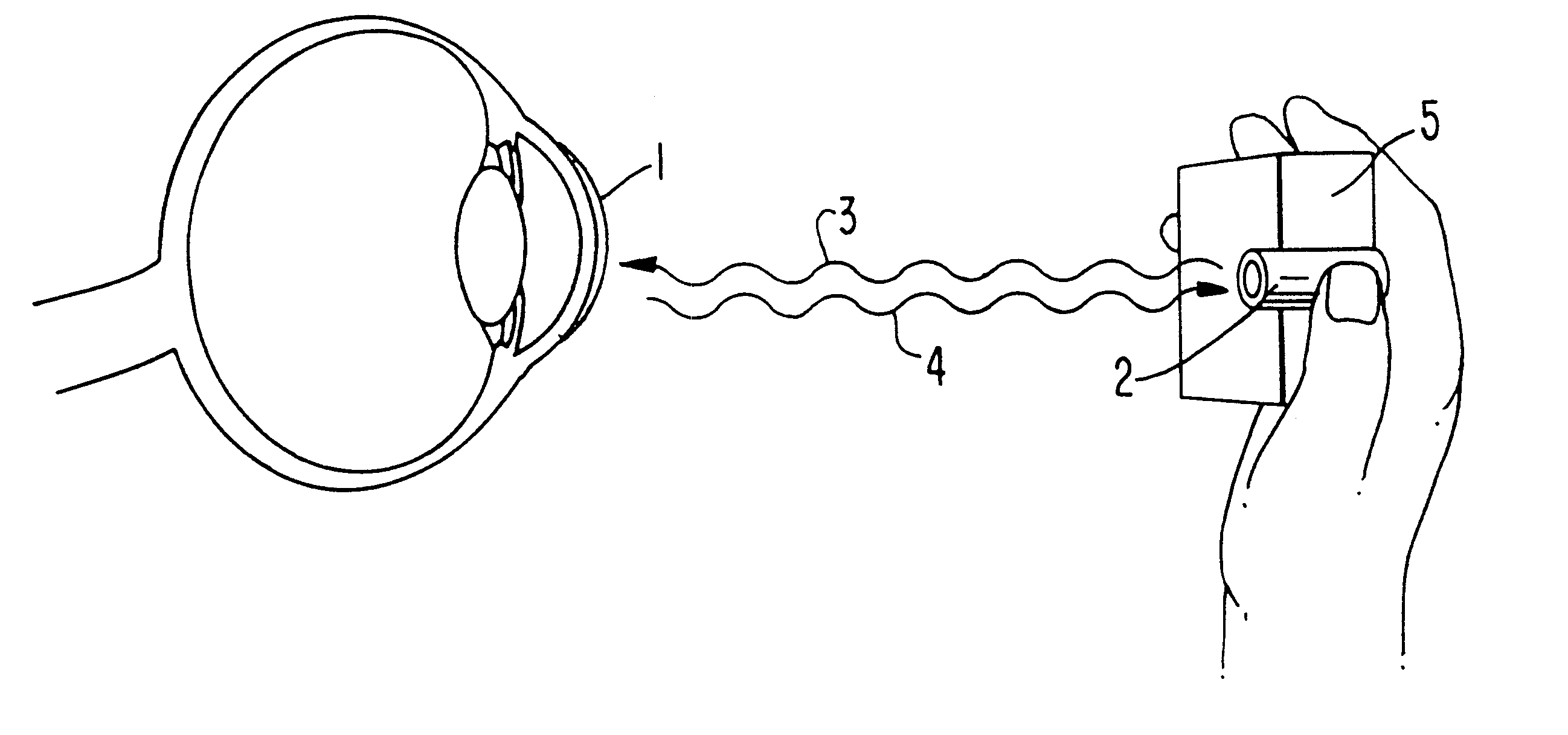
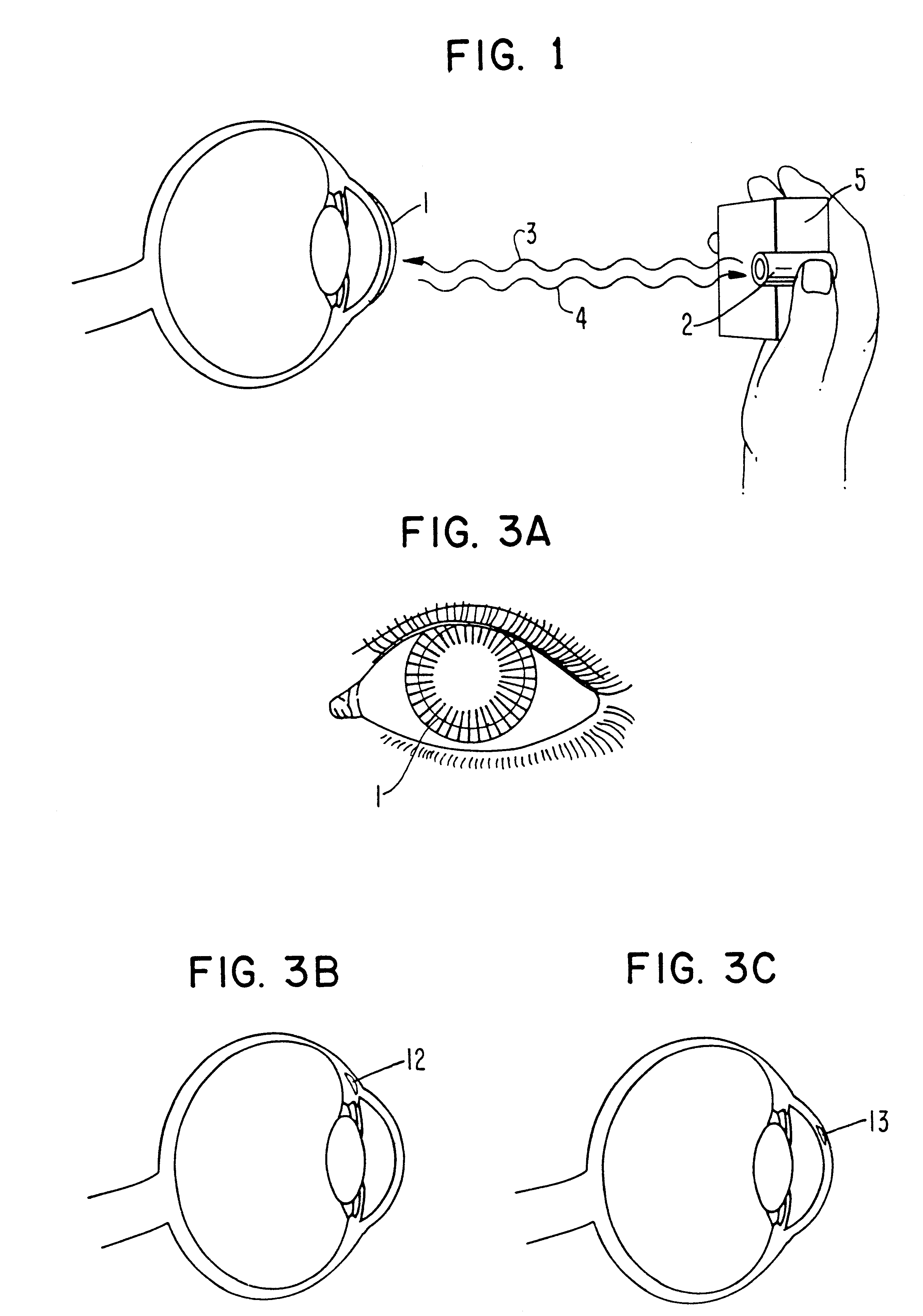
An ophthalmic lens comprising a receptor moiety can be used to determine the amount of an analyte in an ocular fluid which is accessible to light. The receptor moiety can bind either a specific analyte or a detectably labeled competitor moiety. The amount of detectably labeled competitor moiety which is displaced from the receptor moiety by the analyte is measured and provides a means of determining analyte concentration in an ocular fluid, such as tears, aqueous humor, or interstitial fluid. The concentration of the analyte in the ocular fluid, in turn, indicates the concentration of the analyte in a fluid or tissue sample of the body that is not as accessible, such as blood or intracellular fluid.Various noninvasive or minimally invasive methods to measure analytes, particularly glucose, have been described. For example, March, U.S. Pat. Nos. 3,958,560 and 4,014,321, discloses a glucose sensor wherein a patient's eye is automatically scanned using a source of light at one side of ...
Claims
Login to View More Application Information
Patent Timeline
 IPC IPC(8): A61B5/00G01N21/64G01N33/50G01N33/543
CPCA61B5/14532A61B5/1455A61B5/411A61B5/0002Y10S977/905A61B5/00
InventorMARCH, WAYNE FRONT
OwnerEYESENSE AG