
Apparatus and method for depositing large area coatings on non-planar surfaces

a technology of non-planar surfaces and apparatus, which is applied in the direction of coatings, plasma techniques, transportation and packaging, etc., can solve the problems of uniform coating of the substrate, arrays of multiple plasma sources, and inability to uniformly coat such large non-planar surfaces

Inactive Publication Date: 2004-01-27
SABIC INNOVATIVE PLASTICS IP BV
View PDF11 Cites 73 Cited by
  • Summary
  • Abstract
  • Description
  • Claims
  • Application Information

AI Technical Summary

Benefits of technology

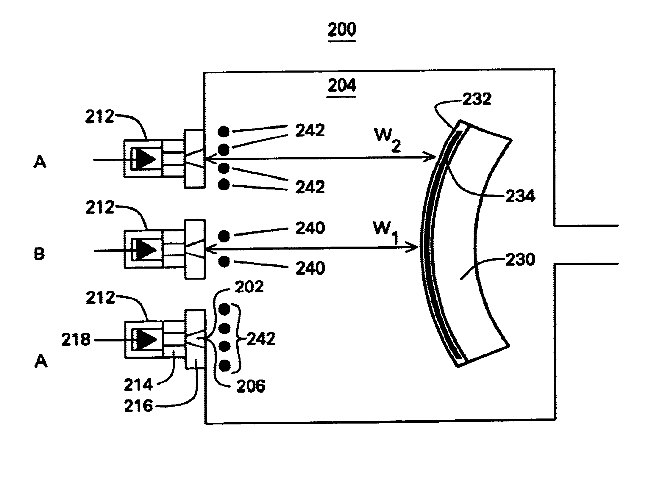
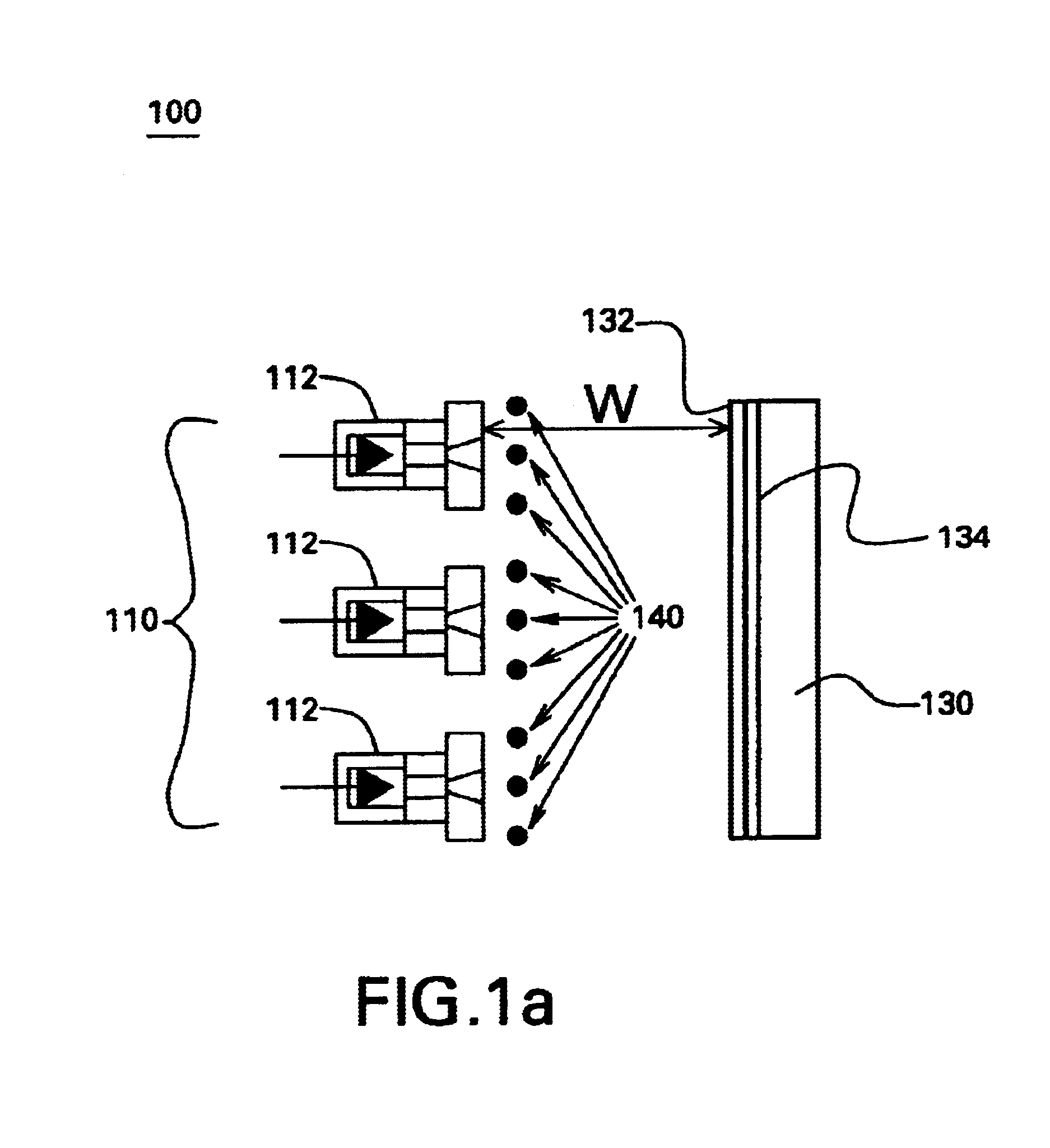
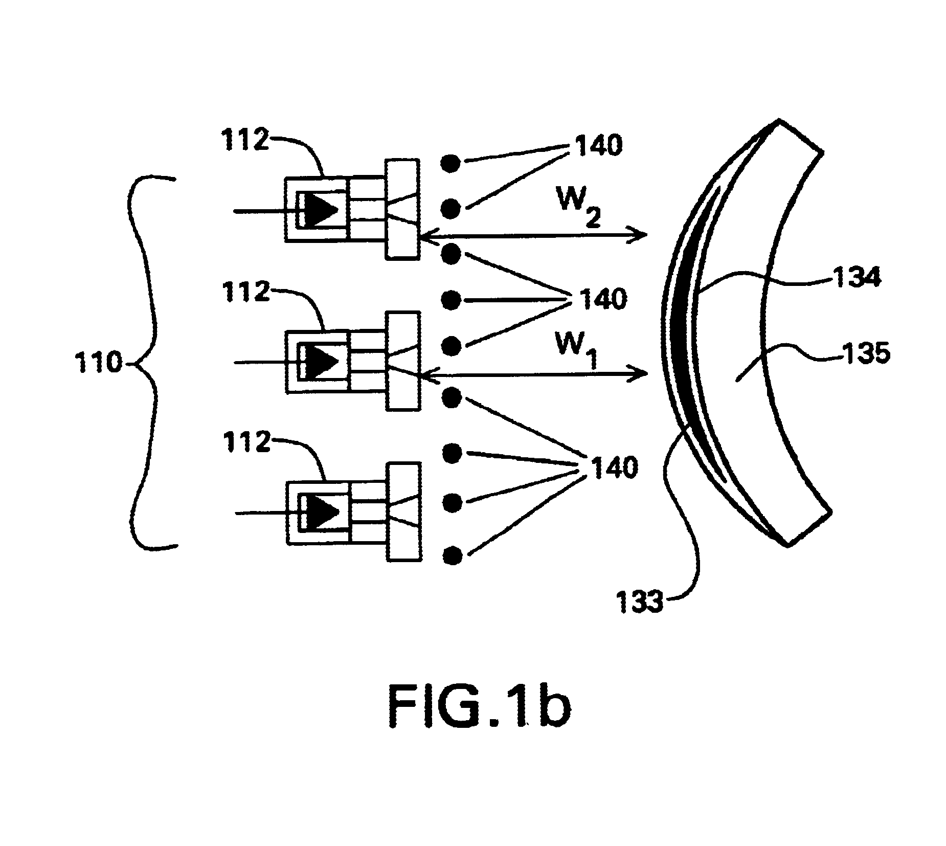
"The present invention provides an apparatus and method for depositing a uniform coating on a non-planar surface of a substrate using a plurality of plasma sources. The invention compensates for changes in processing conditions caused by local variations in the working distance between the plasma source and the substrate surface. The apparatus includes an array of plasma sources, a deposition chamber, and a reactant gas injector. The reactant gas injector injects a different flow rate of reactant gas into each plasma generated by the plasma sources to compensate for changes in the flow rate of the reactant gas caused by the local variations in processing conditions. The method involves evacuating the deposition chamber, generating plasmas from the plasma sources, injecting the reactant gas into the plasmas, flowing the reactant gas and plasmas towards the substrate, and reacting the reactant gas with the plasmas to form the coating on the substrate. The technical effects of the invention include improved uniformity of coating thickness and better substrate processing conditions."

Problems solved by technology

When an array of plasma sources is used to coat a large non-planar surface, however, coating uniformity is adversely affected by the dependence of the coating rate upon variations in the source-to-substrate--or working--distance.
The differences in the coating rate across the surface of a substrate results in a non-uniform coating of the substrate.
Arrays of multiple plasma sources are unable to uniformly coat such large non-planar surfaces.

Method used


Image

  • Apparatus and method for depositing large area coatings on non-planar surfaces
  • Apparatus and method for depositing large area coatings on non-planar surfaces
  • Apparatus and method for depositing large area coatings on non-planar surfaces

Examples


Embodiment Construction

Experimental support for the invention is provided by carrying out experiments in which the precursor flow and the working distance w were varied. The substrate used was a flat polycarbonate substrate, as to better control the effects of these parameters. The ETP source was provided with a injector ring located in the expansion, or deposition, chamber and the reactant gas, or deposition precursor, was vinyltrimethylsilane (hereinafter referred to as "VTMS"). Flow between the VTMS reservoir to the injector ring was regulated and the pressure within the injector ring was monitored. The deposition experiments were performed using either 6 or 12 orifices in the injector ring. The ETP source was fed with 2 slm of argon and a current of 70 A was sent from the cathode to the anode of the ETP source to generate the thermal argon plasma. The pressure in the ETP source, or plasma, chamber was about 600 torr, whereas the pressure in the expansion chamber was about 35 millitorr.

The coating thic...


PUM

PropertyMeasurementUnit
pressureaaaaaaaaaa
pressureaaaaaaaaaa
pressureaaaaaaaaaa

Abstract

A method and apparatus for depositing a uniform coating on a large area, non-planar surface using an array of multiple plasma sources. The apparatus comprises at least one array of a plurality of plasma sources for generating a plurality of plasmas, wherein each of the plurality of plasma sources has a cathode, anode, and an inlet for a non-reactive plasma source gas disposed in a plasma chamber, and at least one reactant gas injector for differentially injecting at least one reactant gas into the plurality of plasmas. The reactant gas injector and substrate are located in a deposition chamber in fluid communication with each plasma chamber. Individual adjustment of the flow of deposition precursor into each of the plasmas generated by the multiple plasma array compensates for changes in substrate processing conditions due to local variations in the working distance between the plasma source and the surface of the substrate.

Description

BACKGROUND OF INVENTIONThe invention relates to an apparatus and method for depositing a uniform coating on a surface of a substrate. More particularly, the invention relates to a method and apparatus for depositing a uniform coating on a surface using multiple plasma sources. Even more particularly, the invention relates to a method and apparatus for depositing a uniform coating on a surface of a substrate using multiple expanding thermal plasma sources.Plasma sources are capable of depositing a large variety of coatings, such as transparent abrasion resistant coatings, transparent UV-filtering coatings, and multi-layer coating packages on a substrate at a high deposition rate. Individual plasma sources, such as expanding thermal plasma (also referred to hereinafter as "ETP") sources, can be used to uniformly coat areas having a diameter in the range of about 10-15 cm.Arrays of multiple plasma sources may be used to coat larger substrate areas. Such large area coating work typicall...

Claims


Application Information

Patent Timeline
Patent Type & Authority Patents(United States)
IPC IPC(8): C23C16/52C23C16/50C23C16/513C23C16/44C23C16/455
CPCC23C16/4558C23C16/52C23C16/513Y10T428/24628
Inventor SCHAEPKENS, MARC
Owner SABIC INNOVATIVE PLASTICS IP BV
Learn More