Color selection electrode implementing a temperature based tension reduction of a shadow mask

a color selection electrode and shadow mask technology, applied in the field of color cathode ray tubes, can solve the problems of poor doming and microphony behavior of cathode ray tubes having tensed shadow masks, the shadow mask is very sensitive to doming and microphony problems, and the cathode ray tubes have tensed shadow masks. , to achieve the effect of reducing the number of shadow masks, poor doming and/or microphony behavior, and

Inactive Publication Date: 2004-02-03
KONINKLIJKE PHILIPS ELECTRONICS NV
View PDF7 Cites 3 Cited by
  • Summary
  • Abstract
  • Description
  • Claims
  • Application Information

AI Technical Summary

Benefits of technology

To this end the cathode ray tube according to the invention is characterized in that the attachment parts comprise bimetal elements to reduce, when the temperature is raised, the distance between the attachment areas more at the center of attached sides of the color selection electrode than at the corners of said sides.
The invention is based on the insight that if the distance between the sides is reduced with a substantially equal amount along the attachment sides, the amount of tension released is less at the center of the side than at the corners. As a consequence, if an evenly distributed tension is released by reducing the distance with an equal amount for each side, the amount being such that at the corners the tension is reduced to substantially zero, there still remains a very considerable tension at the center which remaining tension could lead to plastic deformation. By reducing the distance more at the center than at the corners, the remaining tension is reduced.
Thus the risk of plastic deformation is reduced. It is remarked that in some designs (such as for instance the design shown in WO 98 / 48439) the color selection electrode is unevenly tensioned, i.e. the tension at room temperature is much less in the center than at the corners. In such designs the plastic deformation is less of a problem. Though at high temperatures there is less tension released at the center than at the corners, there was less tension at the center to begin with. However, in such designs the tension at operating temperatures at the center is much less (often less than half) of the maximum tension possible. Compared to such designs, the invention offers the possibility to increase the tension at the center which improves the doming and microphony characteristics of the color selection electrode.
The ratio is chosen to compensate for the effects of a difference in stiffness in the sides. The stiffer the sides are, the smaller the ratio needed, and also the less effect the invention has. For very small ratio (less than 1.3) the positive effects of adding of modifying the bimetal element are relatively small. For high ratio's the effects of the invention are large, but equally large effects may be more easily obtained by stiffening the sides to first reduce the ratio.
Preferably the frame comprises a further bimetal element in the sides perpendicular to the attachment sides to reduce the distance between the attachment sides as whole.

Problems solved by technology

However, an (almost) flat shadow mask is very sensitive to doming and microphony problems.
Cathode ray tubes having tensed shadow mask suffer, however, from a serious problem.
It has, however, been found by inventors that even with a reduction of the distances plastic deformation and / or a relatively poor doming and / or microphony behavior may nevertheless occur in particular at the central area of the mask
As a consequence, if an evenly distributed tension is released by reducing the distance with an equal amount for each side, the amount being such that at the corners the tension is reduced to substantially zero, there still remains a very considerable tension at the center which remaining tension could lead to plastic deformation.
However, in such designs the tension at operating temperatures at the center is much less (often less than half) of the maximum tension possible.

Method used


Image

  • Color selection electrode implementing a temperature based tension reduction of a shadow mask
  • Color selection electrode implementing a temperature based tension reduction of a shadow mask
  • Color selection electrode implementing a temperature based tension reduction of a shadow mask

Examples


Embodiment Construction

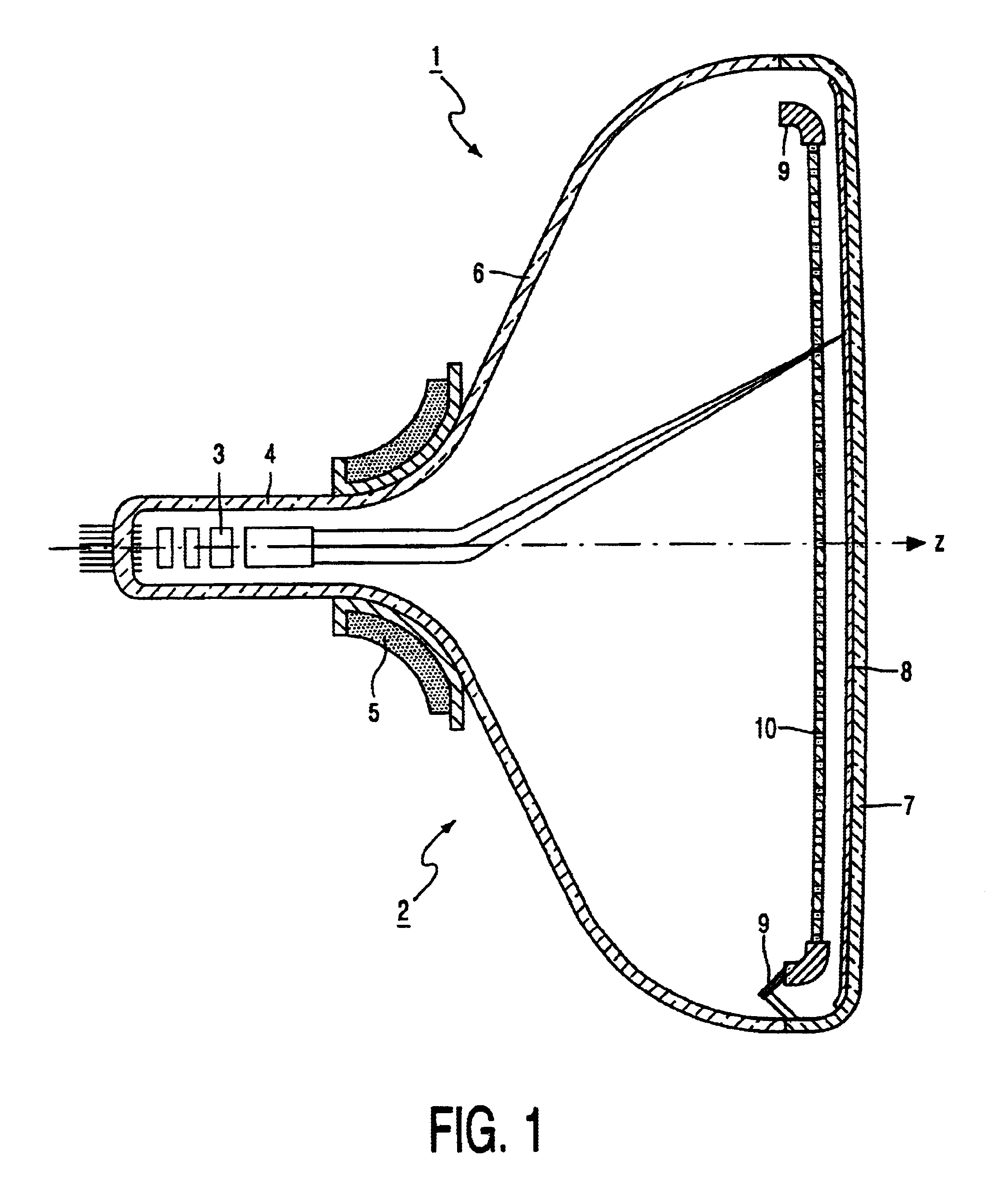
The cathode ray tube 1 shown in FIG. 1 comprises an evacuated glass envelope 2 with a neck 4, a funnel shaped part 6 and a front panel 7, which can either be curved or flat. On the inside of the display panel 7, a display screen 8 having a pattern of for example lines or dots of phosphors luminescing in different colors (e.g., red, green and blue) may be arranged. A substantial rectangular frame 9 supports a thin mask 10 at a short distance form the display screen 8. The mask may be an apertured mask having circular or elongated aperture or a wire mask. The mask may be made of iron or an iron alloy (e.g., a NiFe alloy). During operation of the tube, an electron gun system 3 arranged in the neck 4 generates electron beams. These electron beams pass through the apertures of mask 10 so that the phosphors will emit light. A deflection device 5 ensures that the electron beams systematically scan the display screen.

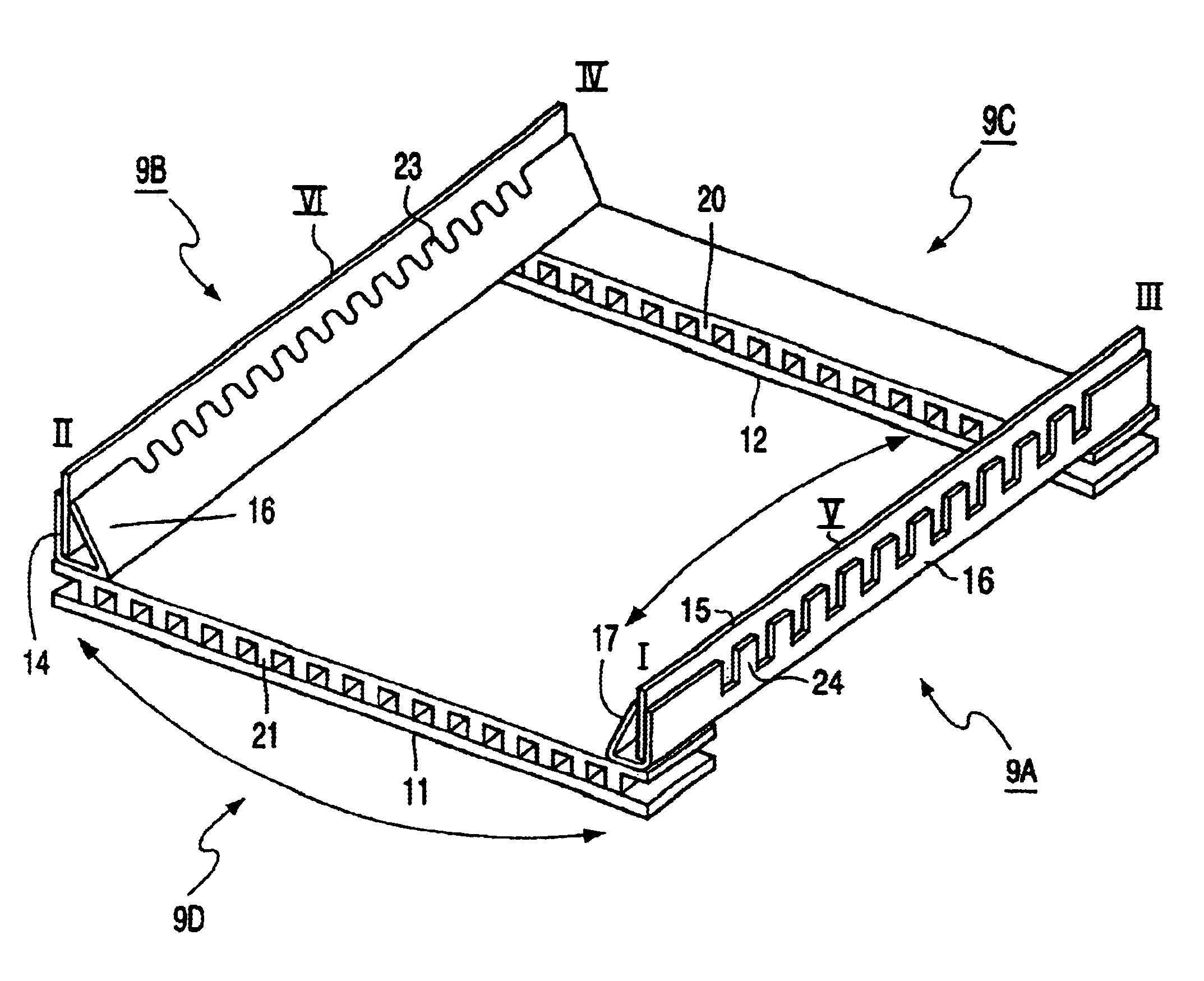
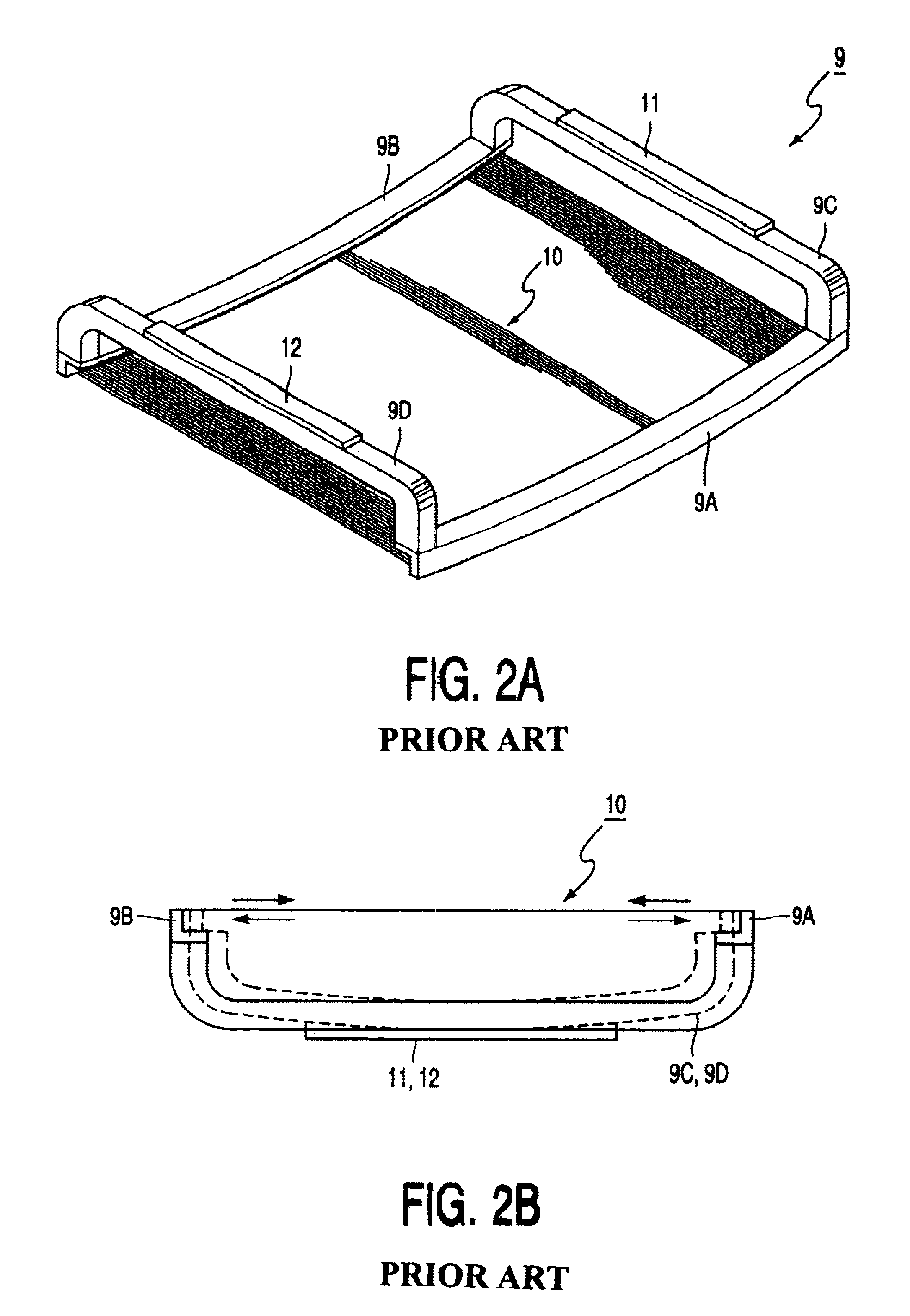
FIGS. 2A and 2B show a color selection electrode as known from U.S. Pat. N...


PUM


Abstract

A cathode ray tube comprises a color selection electrode with a shadow mask fixed to a frame and put under tension. The frame comprises a bimetal element (or bimetal elements) which are constructed such that at a raised temperature the tension is released by reducing the distance between sides of the frame to which the mask is attached. The reduction in distance at the center of the sides exceeds, preferably by a factor 1.5 to 3, the reduction in distance at the corners of said sides.

Description

1. Field of the InventionThe invention relates to a color cathode ray tube having a color selection electrode having a tension mask and a frame, which frame includes a plurality of interconnected parts each forming a side of the frame, whereby the tension mask is stretched under tension and connected at attachment points to at least said two parts, the frame having the capability to cause the attachment points to come closer together when the temperature increases.Such cathode ray tubes are used in for instance television apparatuses and computer monitors.2. Description of the Related ArtColor cathode ray tubes are usually provided with a color selection electrode, to shadow the electron beam(s) coming from the electron gun(s) mounted in the neck such that each beam excites only one color of luminescent material that is deposited on the inside of a display panel. This color selection is achieved by applying a color selection electrode, for instance a shadow mask inside the tube at a...

Claims


Application Information

Patent Timeline
Patent Type & Authority Patents(United States)
IPC IPC(8): H01J29/07
CPCH01J29/073H01J2229/0716H01J2229/0722H01J29/02
Inventor VAN DER WILK, RONALD
Owner KONINKLIJKE PHILIPS ELECTRONICS NV
Why Eureka
Try Eureka