Battery and equipment or device having the battery as part of structure and locally distributed power generation method and power generation device therefor

a technology of battery and equipment, which is applied in the direction of energy input, hydrogen, fuel cells, etc., can solve the problems of unfulfilled scale up, inability to replace, and inability to scale up

Inactive Publication Date: 2004-02-10
KAWASAKI HEAVY IND LTD
View PDF26 Cites 55 Cited by
  • Summary
  • Abstract
  • Description
  • Claims
  • Application Information

AI Technical Summary

Problems solved by technology

(1) Scale up is Impossible.
Even if the number of membranes is increased as a solution to this, the scale up is unfulfilled.
In actuality, the replacement is impossible and the degraded battery is discarded.
However, since the conventional battery is complex in structure, the heat transmitter is not provided.
In some cases, the upper limit temperature is set by using a temperature fuse but any temperature control device is not provided for the battery.
Consequently, the energy density cannot be increased.
However, the conventional batteries of FIGS. 49-52, the following problems arise.
In either case, the battery becomes extremely large and is difficult to practice.
Consequently, the batteries must be connected in parallel, and thereby, the whole structure becomes complex.
In case of the battery of the membrane structure, if an attempt is made to obtain the large capacity, the area of the membrane must be correspondingly increased, and the production cost becomes higher with an increase in the battery capacity.
For this reason, the scale up results in no advantage in production cost.
Since the active materials have a fixed shape such as the plate or cylinder as components of the battery, the whole battery must be replaced when these materials are degraded, because it is impossible to replace only the active materials.
(4) When the batteries are connected in series, a device cost is high and a resistance energy loss in a connected p...

Method used


Image

  • Battery and equipment or device having the battery as part of structure and locally distributed power generation method and power generation device therefor
  • Battery and equipment or device having the battery as part of structure and locally distributed power generation method and power generation device therefor
  • Battery and equipment or device having the battery as part of structure and locally distributed power generation method and power generation device therefor

Examples


seventh embodiment

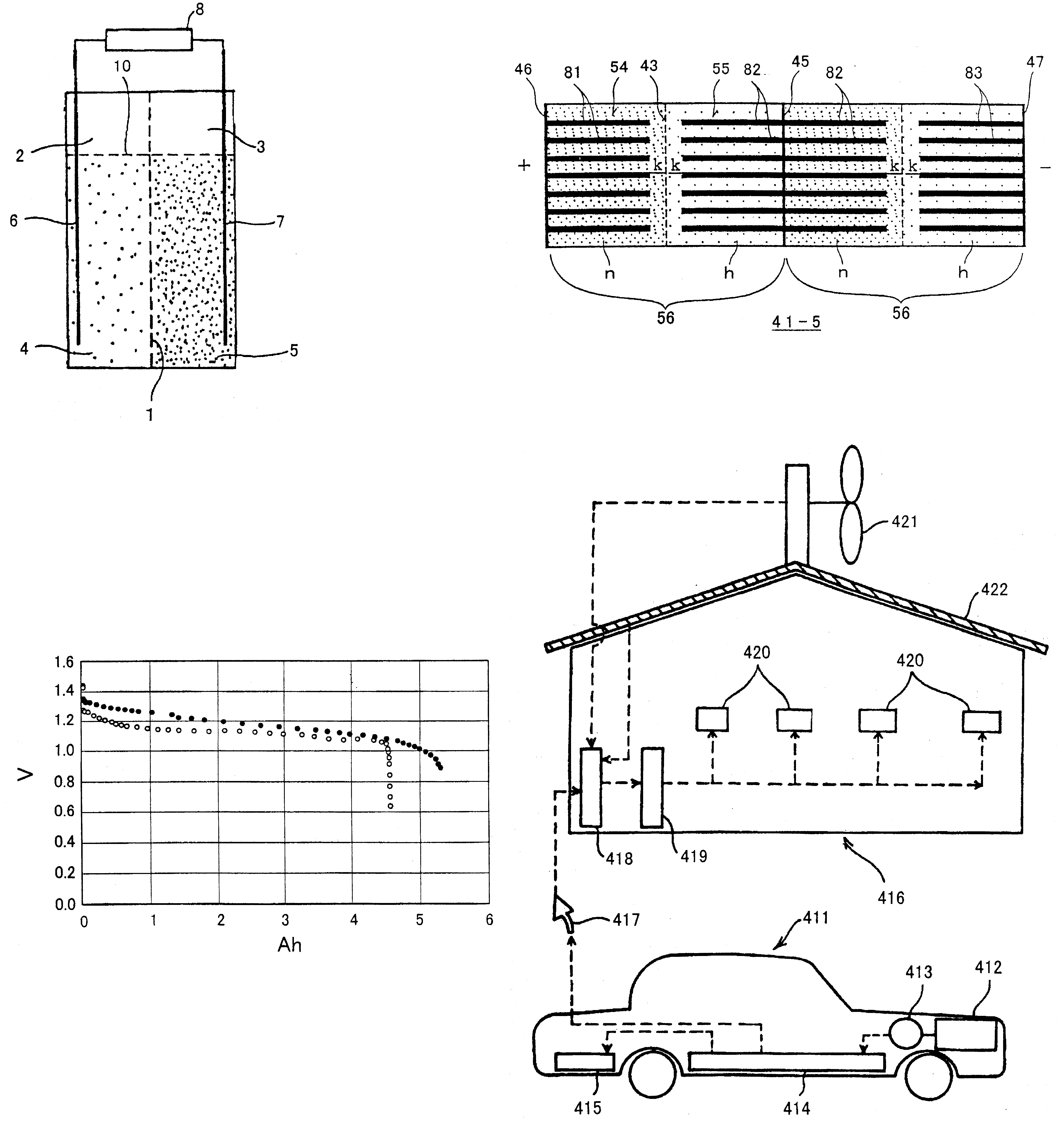
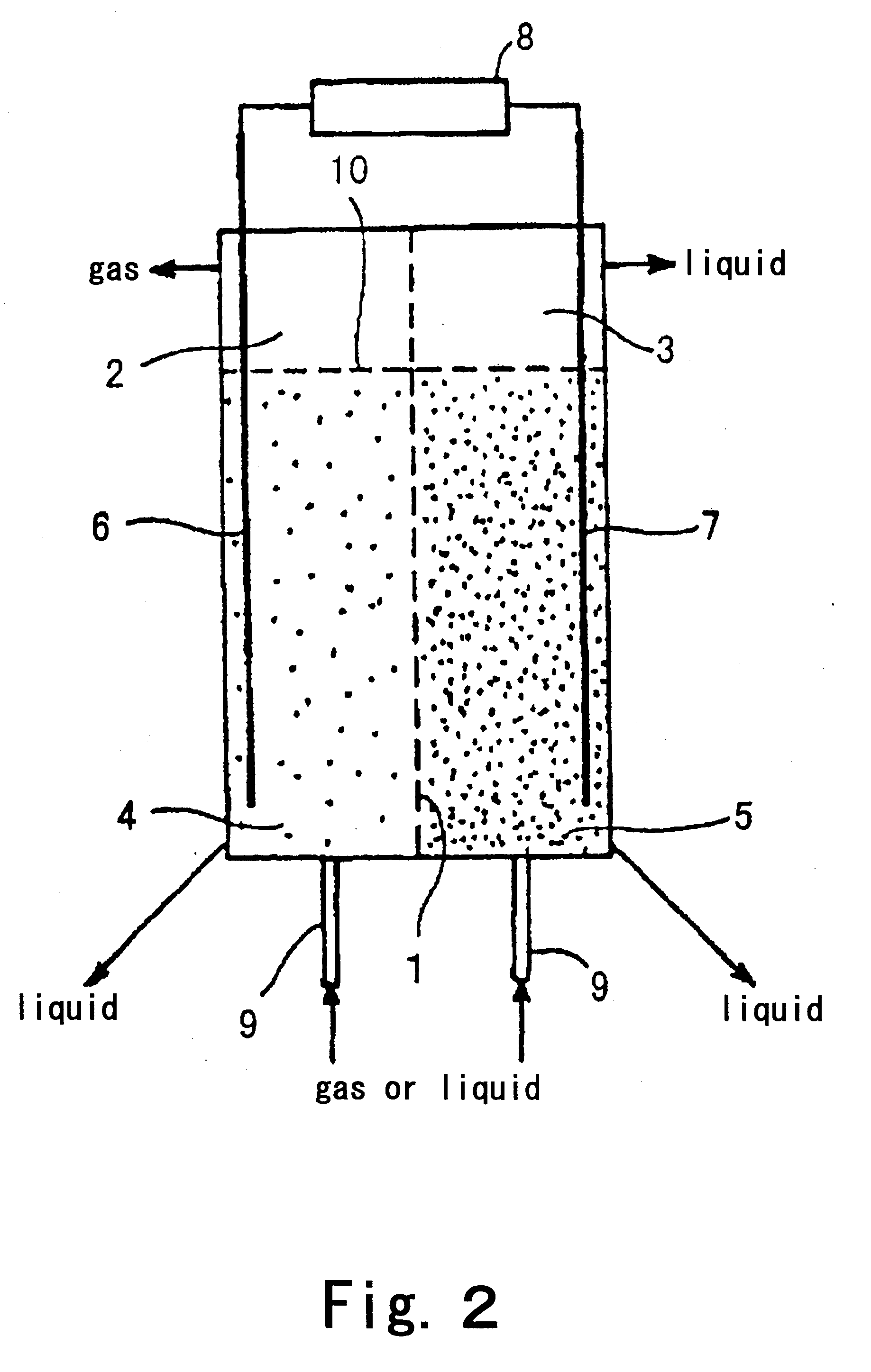
FIGS. 10. 11 show batteries according to a seventh embodiment of the first invention. In this embodiment, there are provided a discharging device for discharging the powdered active material from vessels and a supply device for supplying the powdered active material to the vessels. In addition, there are provided a device for recovering the discharged powdered materials, a device for making up (refilling) the powdered materials, and a device for charging the discharged powdered material by a thermal or chemical reaction.

First of all, charge and discharge of the battery of this embodiment will be explained in detail.

Charge

When the battery is connected to the power generation means 8, an electron is discharged from the power generation means 8 and reaches the anode current collector 6. The electron reacts with the anode powdered material immediately on the anode current collector 6 or while traveling through the anode powdered active material. An anion generated by the fact that the a...

eighth embodiment

FIG. 12 shows a battery according to an eighth embodiment of the first invention. In this embodiment, the hydrogen-occluding alloy is used as the anode powdered active material, hydrogen and hydrogen-containing gas or hydrogen carbide gas or an alcohol-like material or an ether-like material is used as anode agitating (fluidizing) gas, nickel hydroxide is used as the cathode powdered active material, and oxygen or air is used as cathode agitating (fluidizing) gas. As shown in FIG. 12, the anode cell 2 is filled with the powdered hydrogen-occluding alloy and an electrolytic solution 20 and the cathode cell 3 is filled with the powdered nickel hydroxide and an electrolytic solution 21. The fluid fluidizing and dispersing means 9 serves to supply hydrogen to the anode cell 2 and supply oxygen or air to the cathode cell 3. An example of the hydrogen-occluding alloy, La.sub.0.8 (Ce, Nd).sub.0.15 Zr.sub.0.05 Ni.sub.3.8 Co.sub.0.8 Al.sub.0.5 or the like is used. As the electrolytic solutio...

first embodiment

FIG. 13 is a perspective view and a schematic cross-sectional view showing an example of a verification tester of a layered-type three-dimensional battery according to a first embodiment of the second invention and FIG. 14 is a perspective view showing a portion of main components prior to assembling (in a disassembled state) of the verification tester of FIG. 13. As shown in FIG. 13, a layered-type three-dimensional battery 41 is nickel-hydrogen battery. As shown in FIG. 14, the battery is structured to have a pair of two cell (vessel) members 42 each having a square central opening 42a penetrating therethrough in a thickness direction thereof. In the example in FIG. 13, two pairs (four in total) cell members 42 are provided. As shown in FIG. 14, a shallow (in this example, 0.5 mm deep) concave portion 42b is formed annularly at a periphery of the opening 42a of each of the cell members 42. A substantially-square and alkali resistant ion-permeable separator (in this example Teflon ...


PUM


Abstract

A battery comprising powdered active materials and capable of storing a large power, and equipment or device having the battery as parts of its structure, wherein an anode cell (2) of two vessels connected via an ion-passing separator (1) is filled with an anode powdered active material and an electrolytic solution (4), a cathode cell (3) is filled with a cathode powdered active material and an electrolytic solution (5) and conductive current collectors (6, 7) in contact with the powdered active materials are provided in the two vessels.

Description

1. Technical FieldThe present invention relates to a battery and equipment or device having the battery as part of its structure, and a locally-distributed power generation method and a power generation device therefor. More particularly, the present invention relates to a battery of a three-dimensional structure comprising powdered active materials and capable of storing a large power, and equipment or device having the battery as part of its structure, an alkali primary battery and an alkali secondary battery of long lives in which discharge voltages are less likely to be reduced, and a locally-distributed power generation method which utilizes a power of transfer and transport means such as a power-driven two-wheeled vehicle, a power-driven three-wheeled vehicle, a power-driven four-wheeled vehicle, ship, or the like and a power generation device therefor.2. Description of the Related ArtThe present invention relates to a battery. In view of the prior arts, objectives to be achie...

Claims


Application Information

Patent Timeline
IPC IPC(8): C25B9/16H01M4/24H01M2/40H01M4/02H01M10/42H01M2/00H01M4/36H01M10/28H01M4/32H01M10/06H01M10/24H01M4/14H01M6/04H01M10/04H01M8/08B60K8/00B60K25/02B60L11/18C01B3/00F02D29/06H01M4/38H01M4/58H01M6/24H01M6/42H01M6/50H01M8/04H01M8/18H01M10/34H01M10/50H01M14/00H01M50/105H01M50/77
CPCB60L11/1822B60L11/1877B60L11/1879C01B3/0057H01M2/02H01M2/14H01M2/385H01M4/02H01M4/36H01M4/364H01M4/58H01M6/04H01M6/24H01M6/5022H01M6/5038H01M6/5077H01M8/188H01M10/04H01M10/24H01M10/288H01M10/345H01M10/4214H01M10/501H01M10/5016H01M10/5042H01M10/5057H01M10/5093H01M14/00B60L11/184Y02T90/121H01M4/383H01M6/42H01M8/04186H01M10/504H01M2004/027H01M2250/20H01M2250/402H01M2250/405H01M2300/0011H01M2300/0014Y02B90/12Y02E60/124Y02E60/327Y02E60/528Y02T10/7005Y02T10/705Y02T90/128Y02T90/14Y02T90/163Y02T90/32Y02T10/7072Y02T90/169Y02T90/124Y04S30/14Y02B90/16B60L2200/26H01M10/625H01M10/653H01M10/654H01M10/6556H01M10/62H01M10/66Y02P20/133B60L53/80B60L53/64B60L50/66B60L50/64Y02B90/10Y02E60/10Y02E60/32Y02E60/50Y02T10/70Y02T90/12Y02T90/167Y02T90/40H01M50/73Y02P70/50H01M50/105H01M10/42H01M50/489H01M50/531H01M10/615H01M4/583H01M10/28Y02T90/16
Inventor TSUTSUMI, KAZUOATSUTA, TOSHIOKUMAGAI, CHIKANORIKISHIMOTO, MITSUHARUTSUTSUMI, ATSUSHI
Owner KAWASAKI HEAVY IND LTD
Why Eureka
Try Eureka