Pneumatically actuated freight loading system for an aircraft

a pneumatic actuator and aircraft technology, applied in the direction of loading/unloading vehicle arrangment, transportation items, load accommodation, etc., can solve the problems of high wear and tear of drive rollers, and high maintenance cost and effor

Inactive Publication Date: 2004-02-24
AIRBUS OPERATIONS GMBH
View PDF35 Cites 19 Cited by
  • Summary
  • Abstract
  • Description
  • Claims
  • Application Information

AI Technical Summary

Benefits of technology

In the inventive system, it is especially advantageous that the dangers associated with sparking or fire generation from electrical devices is entirely avoided or significantly reduced. The use of pneumatic devices for the roller drive units and / or the freight latching units provides a robust, economical system. Overloading of individual components, or the damage, failure or disruption of any one or more of the individual components or pressurized air lines will not lead to a failure of the total pressurized air line system or network. Furthermore, the inventive freight loading system is not sensitive to moisture or contamination, and requires low maintenance. By minimizing or eliminating current-carrying conductors from the freight loading space of the aircraft, an electrochemical corrosion can be avoided, and electromagnetic effects that are incompatible with or interfere with other systems of the aircraft do not arise. By avoiding the use of electric motors for driving the roller drive units, the overall total system weight is reduced.

Problems solved by technology

These drive rollers suffer a very high wear.
Also, due to the very high effective forces, which arise during normal freight transport operations and particularly also if a container is blocked, the drive rollers and the respectively associated electric motors are very often over-loaded and may thus be damaged.
As a result, such roller drive units often fail and must be replaced or repaired, which leads to a high maintenance cost and effort.
Further problems arise through the use of electric components such as the above-mentioned electric motors respectively associated with each roller drive unit for driving the rollers, as well as electrical control, supply and switching arrangements.
Such electrical components must all be protected against moisture and contamination, and must be electromagnetically shielded, in a complicated and costly manner.
Furthermore, electrochemical corrosion arises, which also increases the sensitivity and likelihood of failure of the components.
In view of the high safety requirements onboard an aircraft, the use of such electric components in the freight compartment or cargo hold of an aircraft is necessarily burdened with a high maintenance, handling, inspection or monitoring, and control effort and expense.
Nonetheless there always exists a possibility of danger, for example, electrical sparking or the starting of a fire due to a malfunction of an electrical component.
Moreover, since each roller drive unit must be respectively equipped with a driving electric motor, the great number of total roller drive units included in a typical aircraft freight loading system results in a high total weight of such a system, which is undesirable in an aircraft.
Furthermore, the inventive freight loading system is not sensitive to moisture or contamination, and requires low maintenance.

Method used


Image

  • Pneumatically actuated freight loading system for an aircraft
  • Pneumatically actuated freight loading system for an aircraft
  • Pneumatically actuated freight loading system for an aircraft

Examples


first embodiment

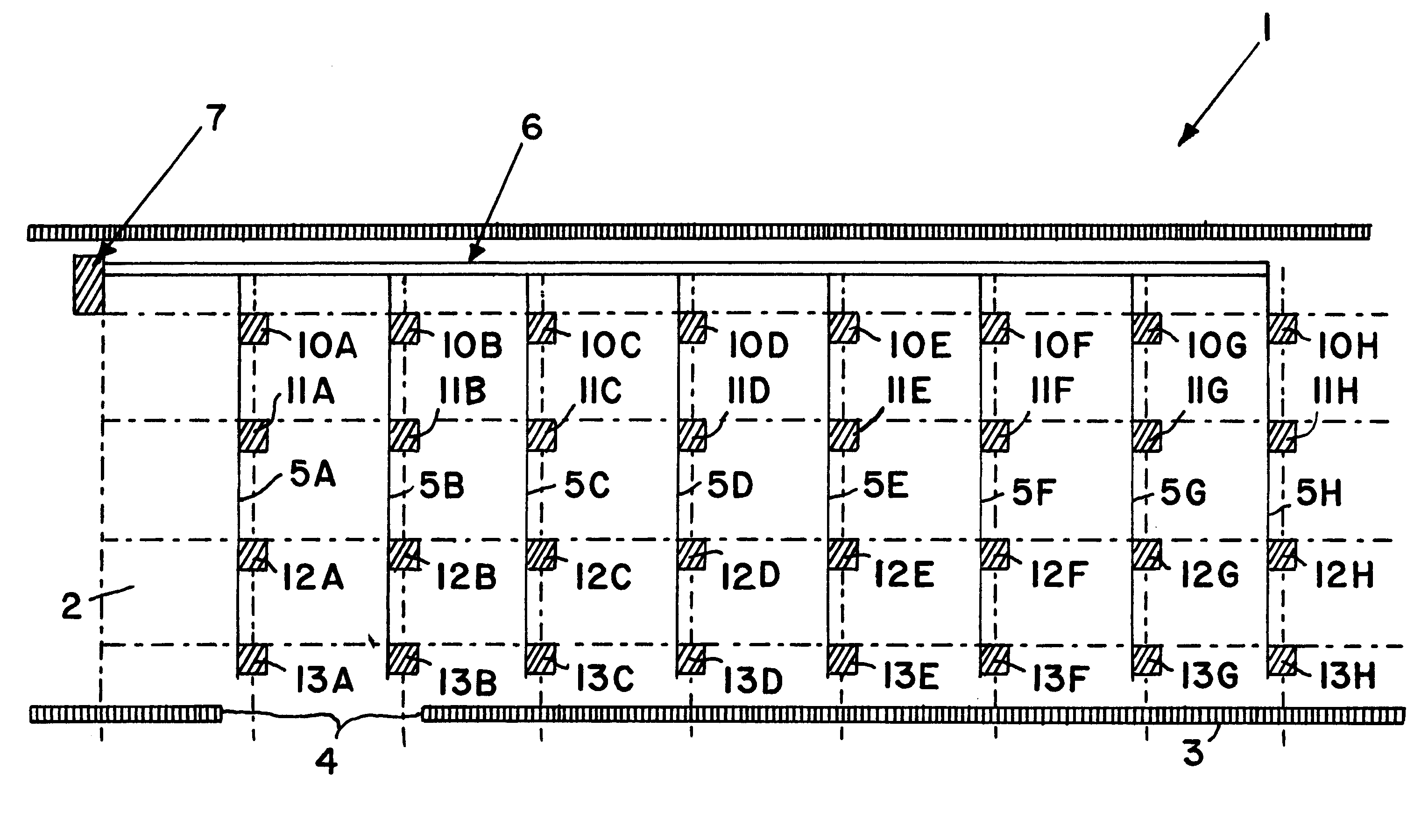
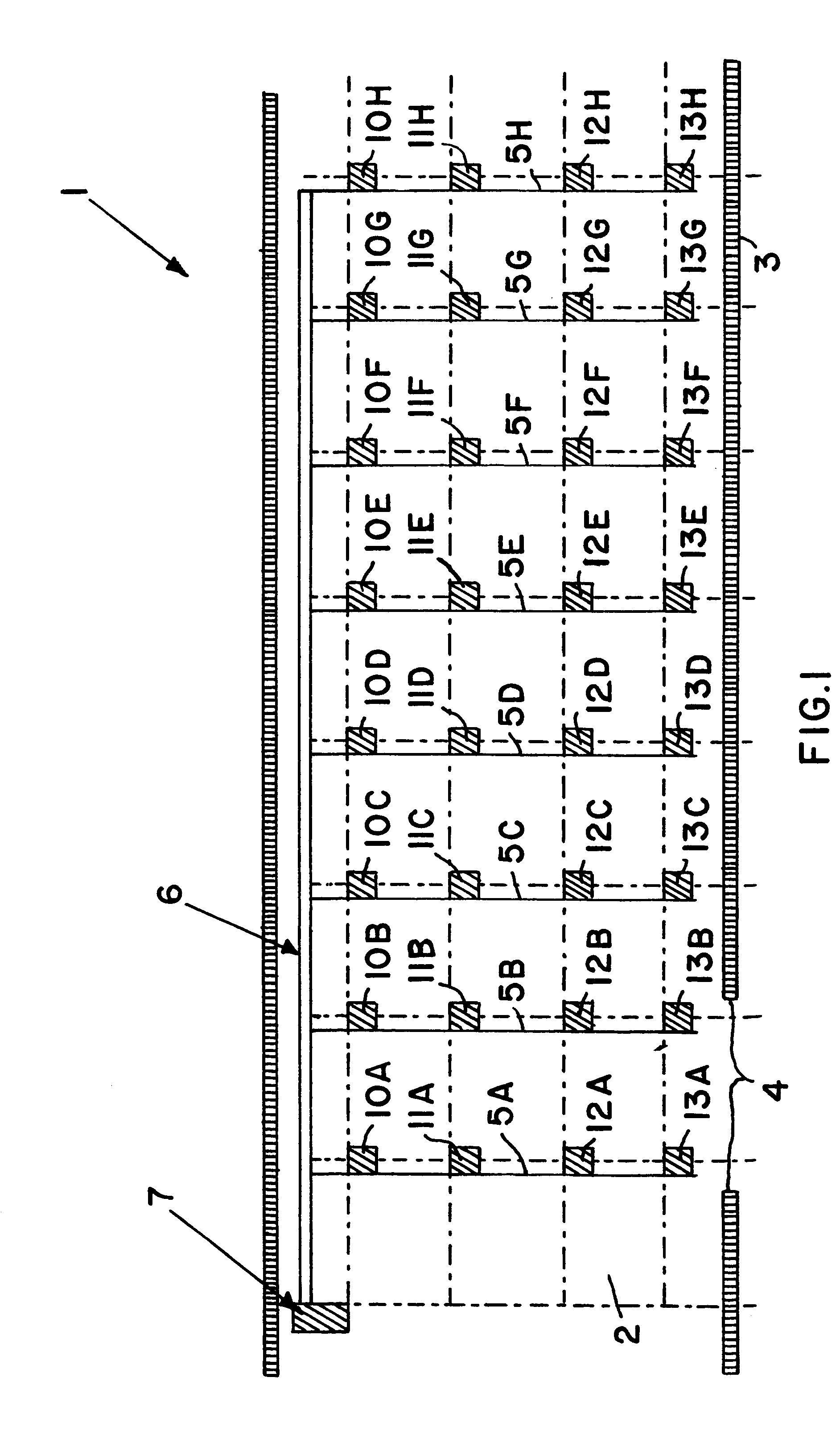
FIG. 1 schematically shows a top plan view of a freight loading system 1, in terms of its layout within the freight compartment or cargo hold 2 of an aircraft. The freight compartment 2 is outwardly bounded by the corresponding structural components (not shown in detail) of the aircraft fuselage 3, whereby an opening 4 is provided through the fuselage 3 for accessing the freight compartment 2. The opening 4 is typically a freight loading doorway or hatch, which is closed by a freight loading door or gate when the process of loading or unloading freight or cargo load units such as containers, pallets, or the like has been completed. Throughout this application, the term "freight load unit" refers to any known unit for loading or unitizing freight or cargo, such as containers, pallets, totes, and the like. These freight loading units may have any conventionally known configuration and construction to be effectively used in connection with the inventive freight loading system 1.

The fre...

second embodiment

Since the present second embodiment of a freight loading system 1' uses electronic control lines 6A with a control voltage of 28 volts, in combination with pneumatic lines and pneumatically actuated devices, the present embodiment realizes an electro-pneumatically functioning freight loading system 1'. In contrast to a conventional purely electrical freight loading system, which must provide electrical power at a relatively high voltage, e.g. 115 volts, to provide the necessary motive power, the present electro-pneumatic freight loading system 1' uses rather low control voltages and control currents, not for driving the drive units and latching units, but merely for operating and controlling the pneumatic control valves. For this reason, the above described problems of electromagnetic interference and electrochemical corrosion suffered by purely electrical freight loading systems, are minimal in the present inventive system. Also, the control lines 6A are arranged only along the out...

third embodiment

This third embodiment of the freight loading system 1", with the pneumatically acting control lines 6A' and SA' to 5H' leading from a central pneumatic control unit 8 or 8A, represents a purely pneumatically operating freight loading system according to the invention. In this embodiment, no electrical devices or current-carrying lines or the like are provided in the freight compartment 2 at all, so that all of the above mentioned dangers and disadvantages of such electrical conductors and devices can be avoided.

As a further alternative embodiment of the invention, only some of the drive units and latching units may be embodied as pneumatic components while other individual components are still embodied as electrically operating components, or only the drive units and latching units in certain areas of the freight loading system are pneumatically operated while the components in other areas of the freight loading system are embodied as electrically operated components according to th...


PUM


Abstract

A freight loading system for an aircraft includes roller drive units for transporting freight load units such as containers or pallets or the like, latching units for latching the freight load units, and control units for operating the drive units and / or the latching units. At least one of the roller drive units and the latching units is embodied as a pneumatically operated component including a pneumatic actuator. Pressurized air is supplied to the pneumatic components through a pressurized air line system. A pneumatic controller provides pneumatic control signals through pneumatic lines to the pneumatic components to achieve a purely pneumatic system, or an electric controller provides electric control signals over electric conductors to control valves for the pneumatic components to achieve a hybrid electro-pneumatic system. The sparking, overloading, and fire hazard problems of fully electric systems are avoided, and the weight, cost, and maintenance are reduced.

Description

The invention relates to a freight loading system for an aircraft, for loading and / or unloading freight load units, such as containers, pallets or the like, wherein the system includes roller drive units for transporting the freight, latching units for latching the freight, and control units for operating and controlling the roller drive units and / or the latching units.BACKGROUND INFORMATIONIn conventional freight loading systems, for example as described in German Patent 44 27 696, it is generally known to arrange roller drive units at a certain spacing distance apart from each other within roller tracks in the freight loading space of an aircraft. The roller drive units are coupled in a force-locking manner to the pieces of freight that are to be transported, such as freight containers, pallets or the like, in order to actively transmit a driving force to the respective freight pieces, so as to move them within the freight loading space of the aircraft. The conventional drive roll...

Claims


Application Information

Patent Timeline
Patent Type & Authority Patents(United States)
IPC IPC(8): B65G13/06B64D9/00B65G13/02B64C1/22B64C1/20
CPCB65G13/06B64D9/00Y02T50/46Y02T50/40
Inventor EILENSTEIN, WILFRIEDSEMPERT, HARTMUT
Owner AIRBUS OPERATIONS GMBH
Why Eureka
Try Eureka