

Beam for weaving and sizing method
Inactive Publication Date: 2004-03-16
ASAHI KASEI KK
View PDF9 Cites 7 Cited by
- Summary
- Abstract
- Description
- Claims
- Application Information
AI Technical Summary
Benefits of technology
The phenomenon in which the sized yarns stick mutually to disable the-weaving operation in the warp beam formed by winding polytrimethylene terephthalate fiber yarns in a sheet form is surmised to be related to a tightening force of the sized yarn wound in the warp beam. Accordingly, when the winding hardness is within the above-mentioned range, the tightening force is suppressed to a minimum level to prevent the mutual stickiness in the sizing beam from occurring to result in the stable weavability and a woven fabric excellent in warp-wise quality.
Problems solved by technology
If polytrimethylene terephthalate fiber yarns are sized at the same stretch ratio S(%) as in the conventional yarns; i.e., approximately -2.4%, the yarns are excessively stretched in the dry zone of the sizing machine, resulting in problems in that yarn breakage may occur due to the wrapping of yarns or single-filaments around rollers in the sizing machine and a winding hardness of an warp beam becomes abnormally high and gradually harder with time, which in turn generates the mutual stickiness of the sized yarns to disturb the shedding motion.
Thus, it was found that the deterioration of warp-wise quality such as tight warp or slack warp occurs to disable the weaving operation.
To solve the above problems, the inventors tried to reduce the pickup of sizing agent to a level lower than that usually adopted, but the mutual stickiness could not be dissolved and weavability became worse.
Moreover, the inventors tried to use some sizing agents which have so lower viscosity as to hardly generate the mutual stickiness, but the mutual stickiness of warp yarns was not satisfactorily improved.
Method used
View moreImage
Smart ImageViewing Examples

Examples
example 18
The polytrimethylene terephthalate yarn of 56 dtex / 24 f obtained from the process 1 (two-stage process of spinning and drawing) was used as a warp yarn and the yarn of 84 dtex / 36 f obtained from the same process was used as a weft yarn. The sizing, beaming and weaving operations were carried out under the same conditions for a WJL as in Example 1, except that an amount of the wax type oil was reduced to 1% by weight (apparent weight base) and to 2.6% by weight on the pure weight base relative to the sizing agent component.
Results thereof were shown in Table 3.
Login to View More PUM
| Property | Measurement | Unit |
|---|---|---|
| Fraction | aaaaa | aaaaa |
| Force | aaaaa | aaaaa |
| Angle | aaaaa | aaaaa |
Abstract
To provide a method for sizing polytrimethylene terephthalate fiber yarns and a warp beam improved in mutual stickiness of the yarns and excellent in weavability,The sizing method according to the present invention is characterized in that the yarns are dried while controlling a stretch ratio S (%) between a squeeze roll and a drying cylinder in a range from -9 to -3% or from -1 to +4%. From the sized yarns thus obtained, a warp beam is formed at a winding tension in a range from 0.09 to 0.22 cN / dtex to have hardness in a range from 65 to 90 degrees.
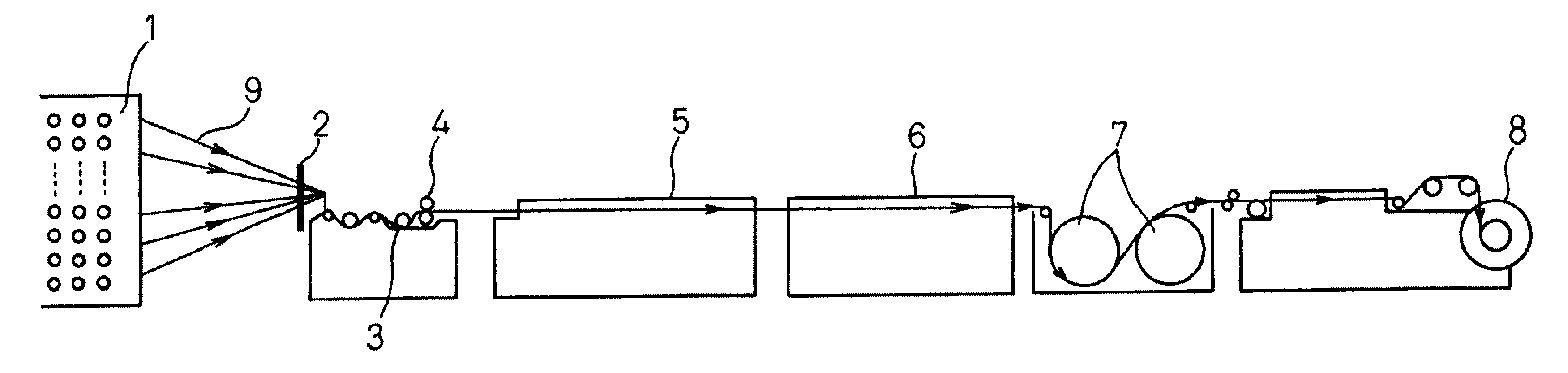
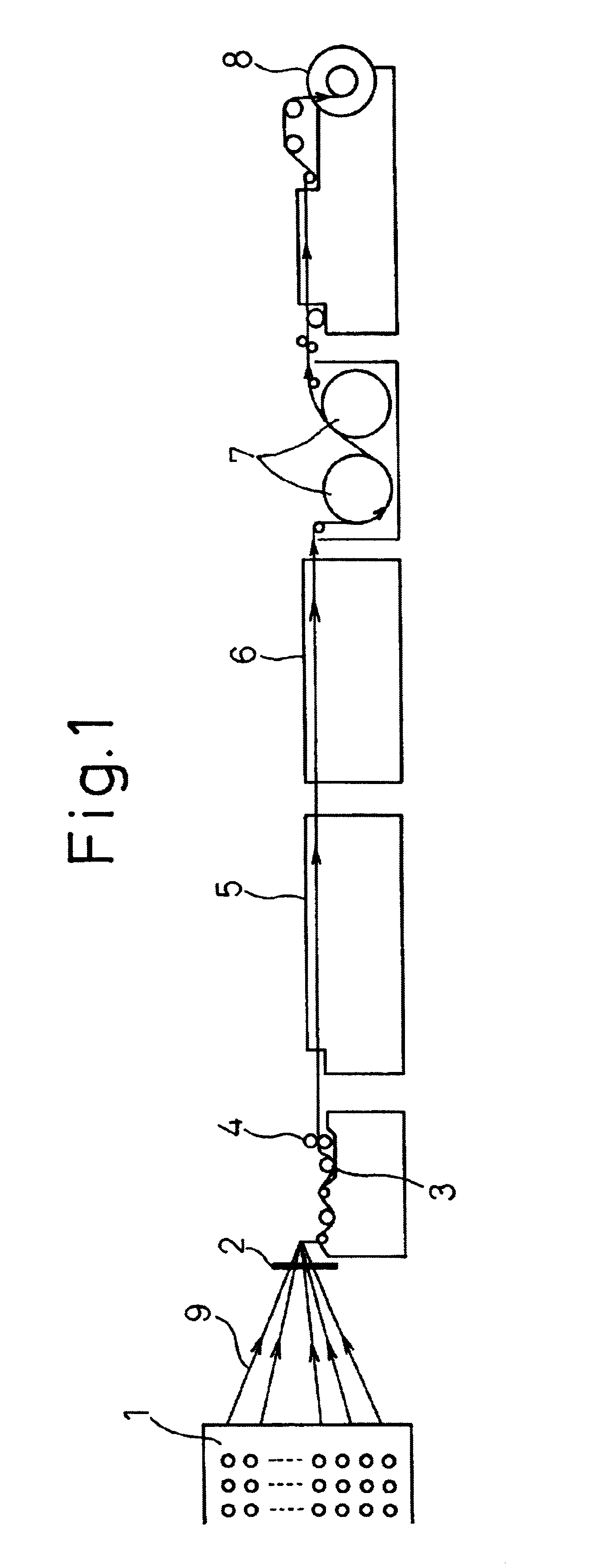
Description
The present invention relates to a warp beam of polytrimethylene terephthalate fiber yarns, a sizing method and a beaming method (that is, a method for forming an warp beam) and, particularly, to a warp beam capable of restricting the mutual stickiness of sized yarns in the warp beam, excellent in weavability and capable of providing a woven fabric having a favorable warp-wise quality.When a woven fabric is produced by using synthetic fiber yarns such as polyester or polyamide as warp yarns, the warp yarns are sized with a sizing agent through a sizing machine as shown in FIG. 1, and are woven by a water jet loom or an air jet loom.In the sizing machine shown in FIG. 1, a plurality of raw yarns 9 mounted to a creel 1 are arranged at a pitch through a reed 2, and after being applied with a sizing agent while dipped in a bath 3 of a solution of the sizing agent, squeezed by squeezing rolls 4 to have a predetermined pickup of the sizing agent. Subsequently, the yarns 9 are dried throug...
Claims
Login to View More Application Information
Patent Timeline
 IPC IPC(8): B65H55/00B65H71/00C08G63/46C08G63/00D02H5/00D02H5/02D06B1/00D02H13/00D02H13/28D02H7/00
CPCD02H5/02D02H7/00D02H13/28B65H2515/12
InventorYAMAMOTO, MITSUYUKIMIZUKI, HIROYUKI
OwnerASAHI KASEI KK