Emitter turn-off thyristors and their drive circuits
a technology of turn-off thyristors and drive circuits, applied in the field of power electronics, can solve the problems of parasitic diodes, increased system size and complexity, and poor safe operating area
- Summary
- Abstract
- Description
- Claims
- Application Information
AI Technical Summary
Benefits of technology
Problems solved by technology
Method used
Image
Examples
first embodiment
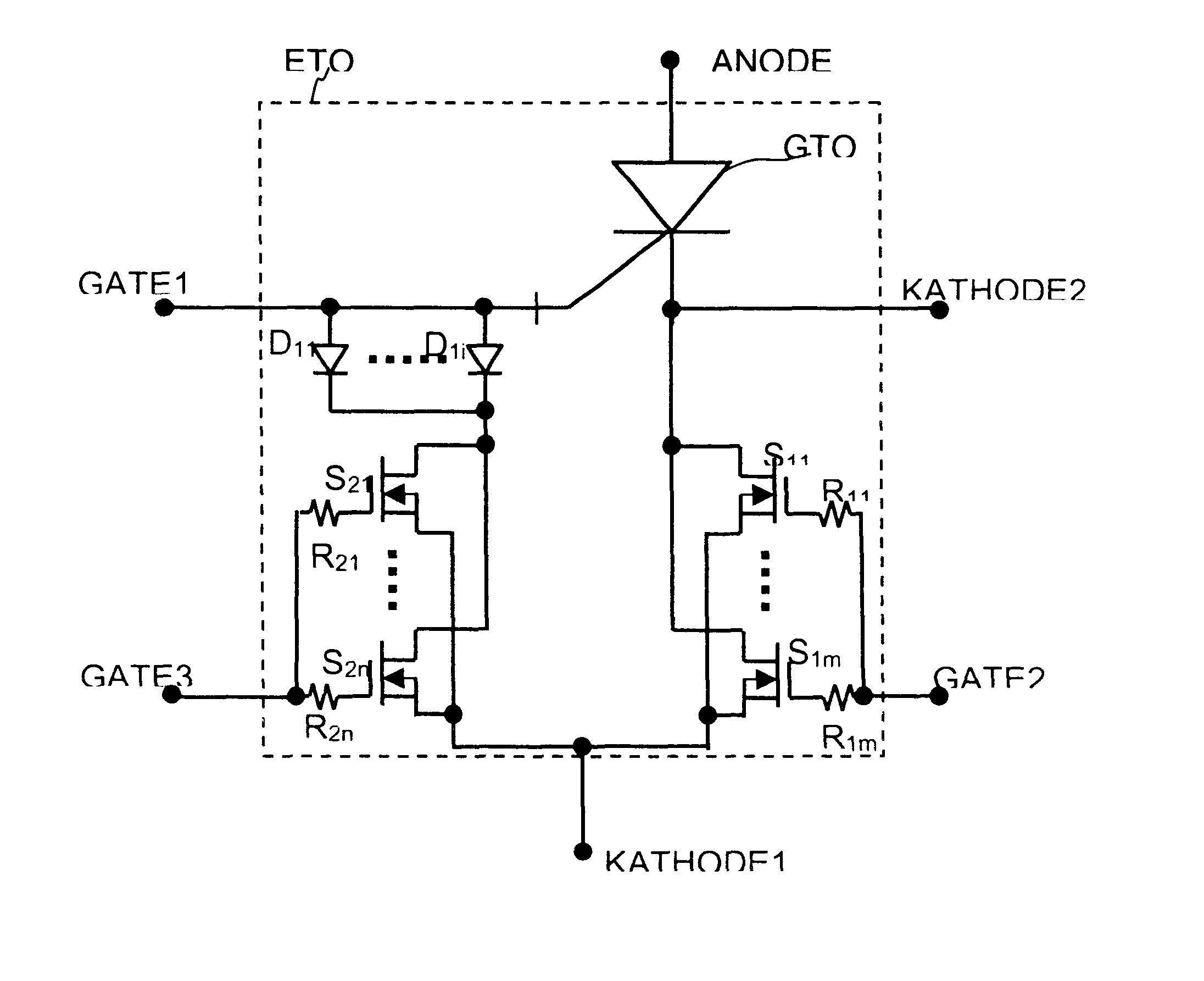
Referring again to the drawings, and more particularly now to FIG. 2, there is shown an equivalent circuit diagram of an ETO thyristor according to the invention. In this structure, a number (m pieces, in the depicted example, m=68) of paralleled MOSFETs, S.sub.11.about.S.sub.1m, are used to build the emitter switch. There are also resistors R.sub.11.about.R.sub.1m connect to the gates of the MOSFETs. The drains of S.sub.11.about.S.sub.1m connect to the cathode of the GTO thyristor. Between the cathodes of emitter switch S.sub.11.about.S.sub.1m and the gate of the GTO thyristor, there is a series circuit of a gate switch and a gate diode. A number (n pieces, in the depicted example, n=12) of paralleled MOSFETs, S.sub.11.about.S.sub.1n, are used to build the gate switch. There are resistors R.sub.11.about.R.sub.1n connect to the gates of the MOSFETs. And there are a number (i pieces, in the depicted example, i=12) of paralleled diodes, D.sub.11.about.D.sub.1i are used to build the ga...
second embodiment
Referring now to FIG. 3 there is an equivalent circuit diagram of an ETO thyristor according to the invention. In this structure, a number (m pieces, in the depicted example, m=68) of paralleled MOSFETs, S.sub.11.about.S.sub.1m, are used to build the emitter switch. There are also resistors R.sub.11.about.R.sub.1m connect to the gates of the MOSFETs. The drains of S.sub.11.about.S.sub.1m connect to the cathode of the GTO thyristor. A number (n pieces, in the depicted example, n=12) of paralleled insulated gate bipolar transistors (IGBTs) S.sub.11.about.S.sub.1n, are used to build the gate switch. There are also resistors R.sub.11.about.R.sub.1n connect to the gates of the IGBTs. The anodes of S.sub.11.about.S.sub.1n connect the gate of GTO thyristor. The sources of S.sub.11.about.S.sub.1m and the sources of S.sub.11.about.S.sub.1n are connected together. The anode of the GTO thyristor, ANODE, and the sources of S.sub.11.about.S.sub.1n and S.sub.11.about.S.sub.1m, KATHODE1, are defin...
third embodiment
Referring now to FIG. 4 there is an equivalent circuit diagram of an ETO thyristor according to the invention. In this structure, a number (mn pieces, in the depicted example, m=68) of paralleled MOSFETs, S.sub.11.about.S.sub.1m, are used to build the emitter switch. There are also resistors R.sub.11.about.R.sub.1m connect to the gates of the MOSFETs. The drains of S.sub.11.about.S.sub.1m connect to the cathode of the GTO thyristor. Between the cathodes of emitter switch S.sub.11.about.S.sub.1m and the gate of the GTO thyristor, there is a series circuit of a gate switch S.sub.2 and a capacitor C.sub.1. S.sub.2 has three terminals among which G is the control input. There is a diode D.sub.1 which is connected in parallel with C.sub.1. And there is a diode D.sub.2 which is connected in parallel with S.sub.2. The anode of the GTO thyristor ANODE, and the sources of S.sub.11.about.S.sub.1n KATHODE1 are defined the anode and the cathode of ETO thyristor respectively. There are four cont...
PUM
 Abstract
Description
Claims
Application Information
 - R&D
- Intellectual Property
- Life Sciences
- Materials
- Tech Scout
- Unparalleled Data Quality
- Higher Quality Content
- 60% Fewer Hallucinations
Browse by: Latest US Patents, China's latest patents, Technical Efficacy Thesaurus, Application Domain, Technology Topic, Popular Technical Reports.
© 2025 PatSnap. All rights reserved.Legal|Privacy policy|Modern Slavery Act Transparency Statement|Sitemap|About US| Contact US: help@patsnap.com


