Integrated electric power and synthetic fuel plant

a technology of electric power and synthetic fuel, applied in the direction of combustible gas production, liquid degasification, separation processes, etc., can solve the problems of uneconomical transportation of syngas over long distances, unsatisfactory air pollution problems, and high cost of removing undesirable compounds, so as to maintain or lower the undesirable components of exhaust gas emissions

Inactive Publication Date: 2004-03-30
RICH JR JOHN W
View PDF6 Cites 22 Cited by
  • Summary
  • Abstract
  • Description
  • Claims
  • Application Information

AI Technical Summary

Benefits of technology

It is an object of this invention to maintain or lower the undesirable components of exhaust gas emissions of an electric power plant

Problems solved by technology

The combustion of carbonaceous materials, such as coal, in the production of electricity can cause undesirable air pollution problems because the flue gases may contain toxic heavy metals, such as mercury, along with other undesirable byproducts such as SO.sub.x, CO and NO.sub.x.
Since it is very expensive to remove undesirable compounds from the flue gases of electric power plants, it has been proposed to remove the compounds from the carbonaceous materi

Method used


Image

  • Integrated electric power and synthetic fuel plant
  • Integrated electric power and synthetic fuel plant

Examples


Embodiment Construction

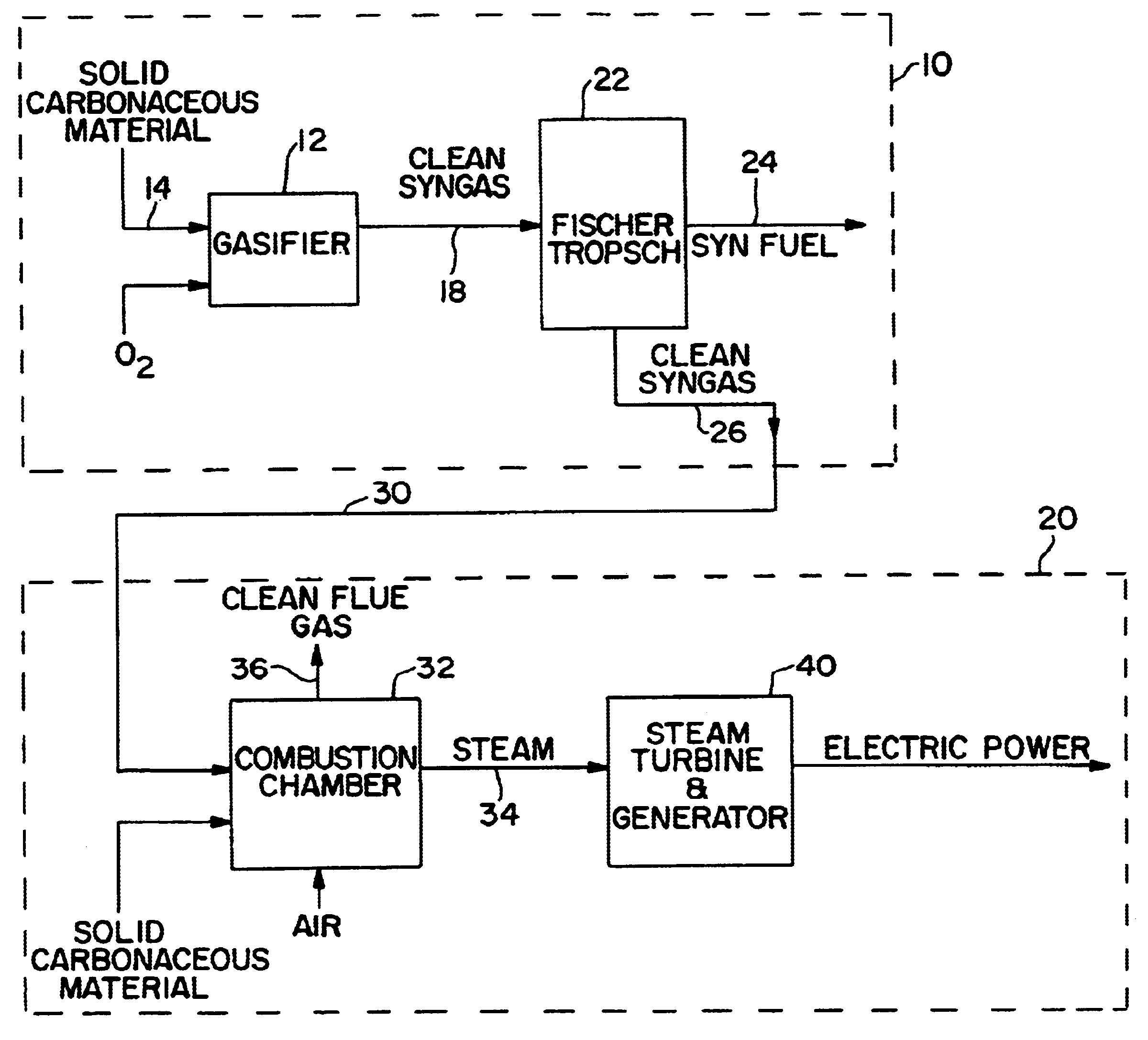
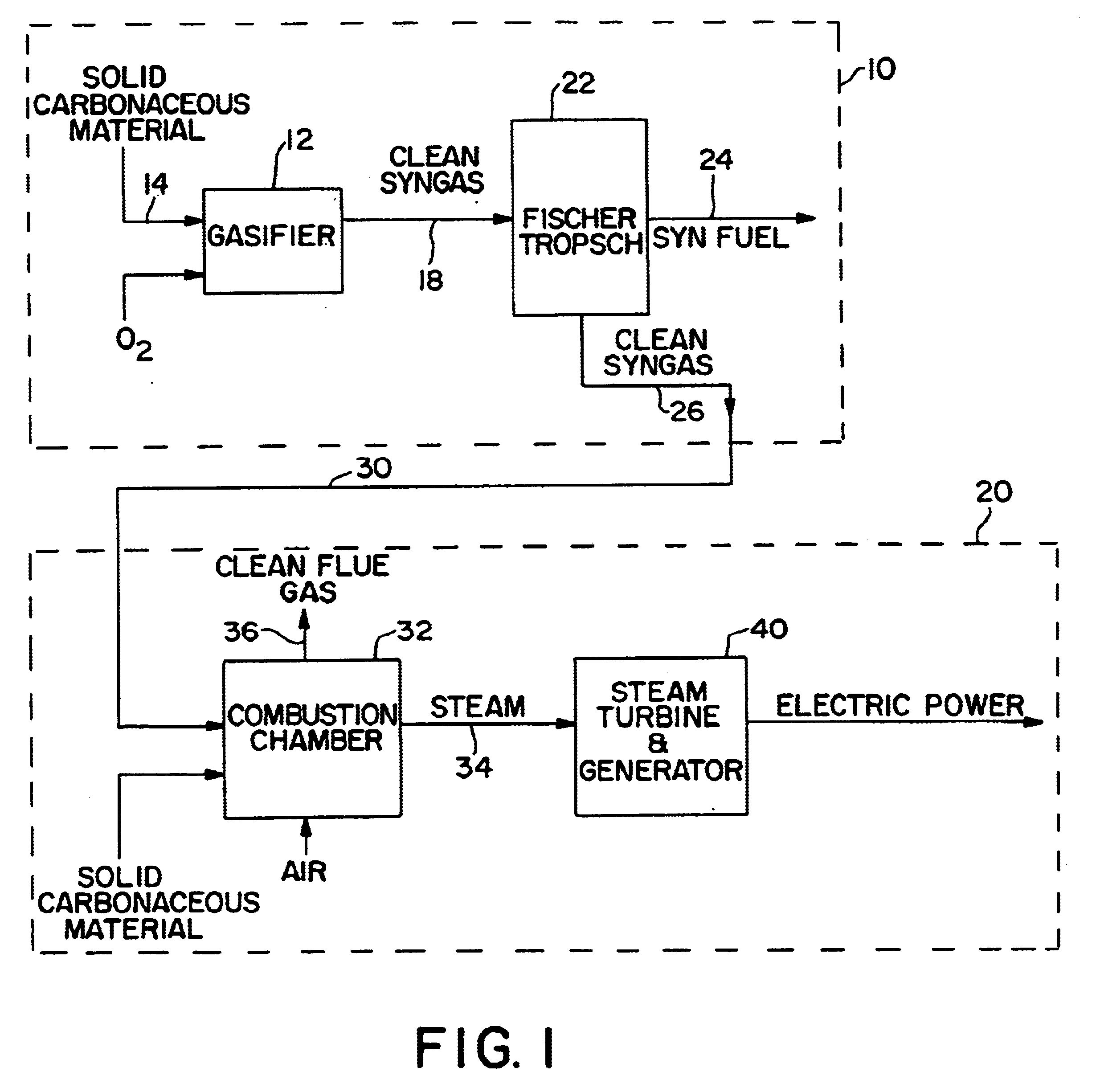
FIG. 1 schematically illustrates a synthetic fuel plant 10 connected to an adjacent pre-existing electric power plant 20. The synthetic fuel plant 10 comprises a gasification reactor 12, or gasifier. Solid carbonaceous raw materials are fed through inlet 14 of the gasifier 12. Inside the gasifier 12, the carbonaceous materials are contacted with oxygen and are exothermically reacted under pressure and converted to substantially sulfur and nitrogen-free synthetic gas, or syngas.

The clean syngas is discharged from the gasifier 12 via line 18 and directed into a Fischer-Tropsch reactor 22. In the Fischer-Tropsch reactor 22, the syngas is contacted with a catalyst which synthesizes a portion of the syngas into synthetic liquid fuel, or synfuel. The synfuel is removed from the Fischer-Tropsch unit via line 24. The unreacted syngas is recovered via line 26 and is transported along piping 30.

The unreacted syngas flowing within piping 30 is charged into the combustion chamber 32 of the elec...


PUM


Abstract

A power plant generates electricity from carbonaceous material and fuel provided by a syngas plant such that clean electric power is generated and flue gas emissions are minimized. The syngas plant produces liquid fuel and unreacted syngas in a Fischer-Tropsch reactor, and the unreacted syngas is conducted to a combustion chamber of the power plant for use as a clean fuel moiety of the carbonaceous material burned in the combustion chamber. The unreacted syngas enables the electric power plant to operate below acceptable environmental limits in producing steam to generate electricity.

Description

The present invention relates to clean electric power generation in which toxins in flue gas emissions are minimized for a given power output.It is well known in older electric power plants to burn solid carbonaceous material in the presence of an oxygen-containing gas in a combustion chamber to produce heat which creates steam that is fed to a turbine where it is expanded to produce electricity. The combustion of carbonaceous materials, such as coal, in the production of electricity can cause undesirable air pollution problems because the flue gases may contain toxic heavy metals, such as mercury, along with other undesirable byproducts such as SO.sub.x, CO and NO.sub.x. To maintain, or improve, air quality, it is important to minimize the production of these undesirable compounds.Since it is very expensive to remove undesirable compounds from the flue gases of electric power plants, it has been proposed to remove the compounds from the carbonaceous materials prior to combustion.Fu...

Claims


Application Information

Patent Timeline
IPC IPC(8): C10J3/46C10J3/06C10J3/00C10J3/02C10G2/00
CPCC10G2/32C10J3/06C10J3/46C10J2300/093C10J2300/0959C10J2300/1215C10J2300/1659C10J2300/1675C10J2300/1687Y02E20/18Y02E20/16
Inventor RICH, JR., JOHN W.
Owner RICH JR JOHN W
Why Eureka
Try Eureka