Self-tensioning pedal drive mechanism for a human powered boat

a pedal drive mechanism and pedal drive technology, which is applied in the direction of propulsive transmission, marine propulsion, vessel construction, etc., can solve the problems of absorbing ropes or belts tend to slip, and the system absorbs too much of the cyclist's energy to actuate, etc., to achieve less expense and faster speed

Inactive Publication Date: 2004-03-30
FREE JAMES JACOB
View PDF26 Cites 16 Cited by
  • Summary
  • Abstract
  • Description
  • Claims
  • Application Information

AI Technical Summary

Benefits of technology

It is further an object of this invention to provide a drive system that is entirely maintenance free, and wherein the entire drive system lends itself to being totally waterproof wherein the interior workings may be non-corrosion-resistant, and therefore of lesser expense.
It is another object of this invention to provide a drive with a narrower strut, and therefore faster speeds.

Problems solved by technology

The fact that even though a toothed belt may be used as in White (5,547,406 et el), Lekhtman (U.S. Pat. No. 6,231,408), Marinc (U.S. Pat. No. 5,580,288), et el, doesn't ease the condition of energy loss due to deforming soft material as it engages into and twists around a pulley.
This type of system absorbs too much of the cyclist's energy to actuate it.
Furthermore, in higher torque situations, ropes or belts will tend to slip.
Toothed belts can be built large enough by those trained in the art to prevent slippage with medium-high torque propellers, but by the time this problem has been solved, he material deformation energy loss as the drive is actuated will have been way too high.
Due to the fact that the Flying Fish chain was operated near its breaking point, it spun easily, but could only be used in racing.
Although this characteristic allows for easy pulley diameter / gear ratio change adaptation, it is heavier, more complex because of more moving parts, requires extra power to operate the extra shaft, chain / belt and bearings, and is extremely difficult to maintain the tension of both or more belts or chains.
Although Eide (U.S. Pat. No. 5,011,441), et el simplify the drive over those using secondary shafting to the use of just two shafts, reliability problems were present due to derailing and / or chain breakage.
Although the drive unit of Eide et el would provide chain operation with low power loss in a twisted environment, it would often prematurely break due to the chain not being heavy duty enough as well as operating in a continually loosening or loosening and sometimes tightening situation.
For those and other reasons, chains, and ultimately sprockets would wear out faster.
In a non constantly tensioned system, if a single bolted idler or jack shaft were to get repositioned, or if the drive system was to experience a chain which lengthens, the system will jam, skip or undergo teething problems.

Method used


Image

  • Self-tensioning pedal drive mechanism for a human powered boat
  • Self-tensioning pedal drive mechanism for a human powered boat
  • Self-tensioning pedal drive mechanism for a human powered boat

Examples


embodiment # 1

ALTERNATIVE EMBODIMENT #1

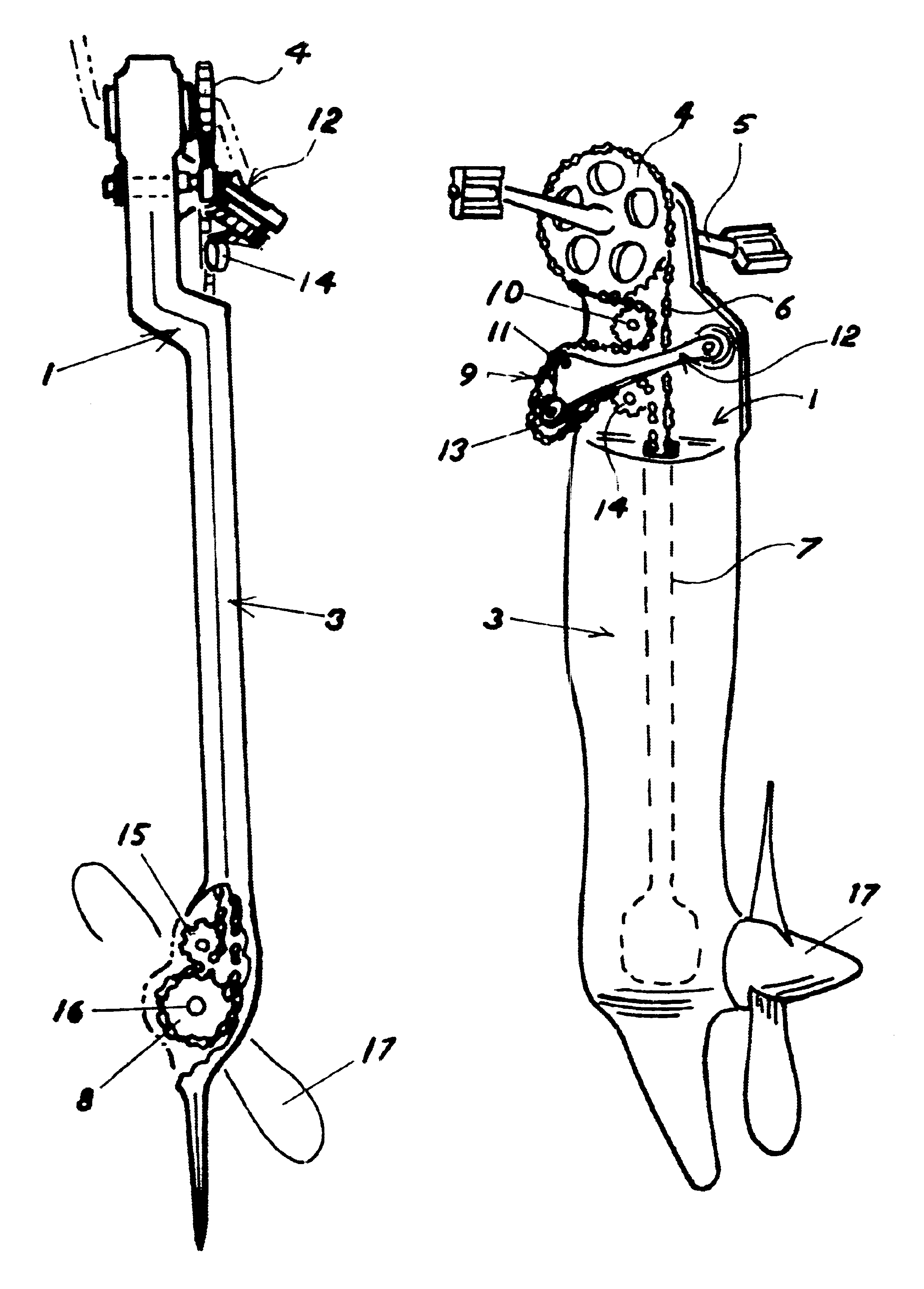
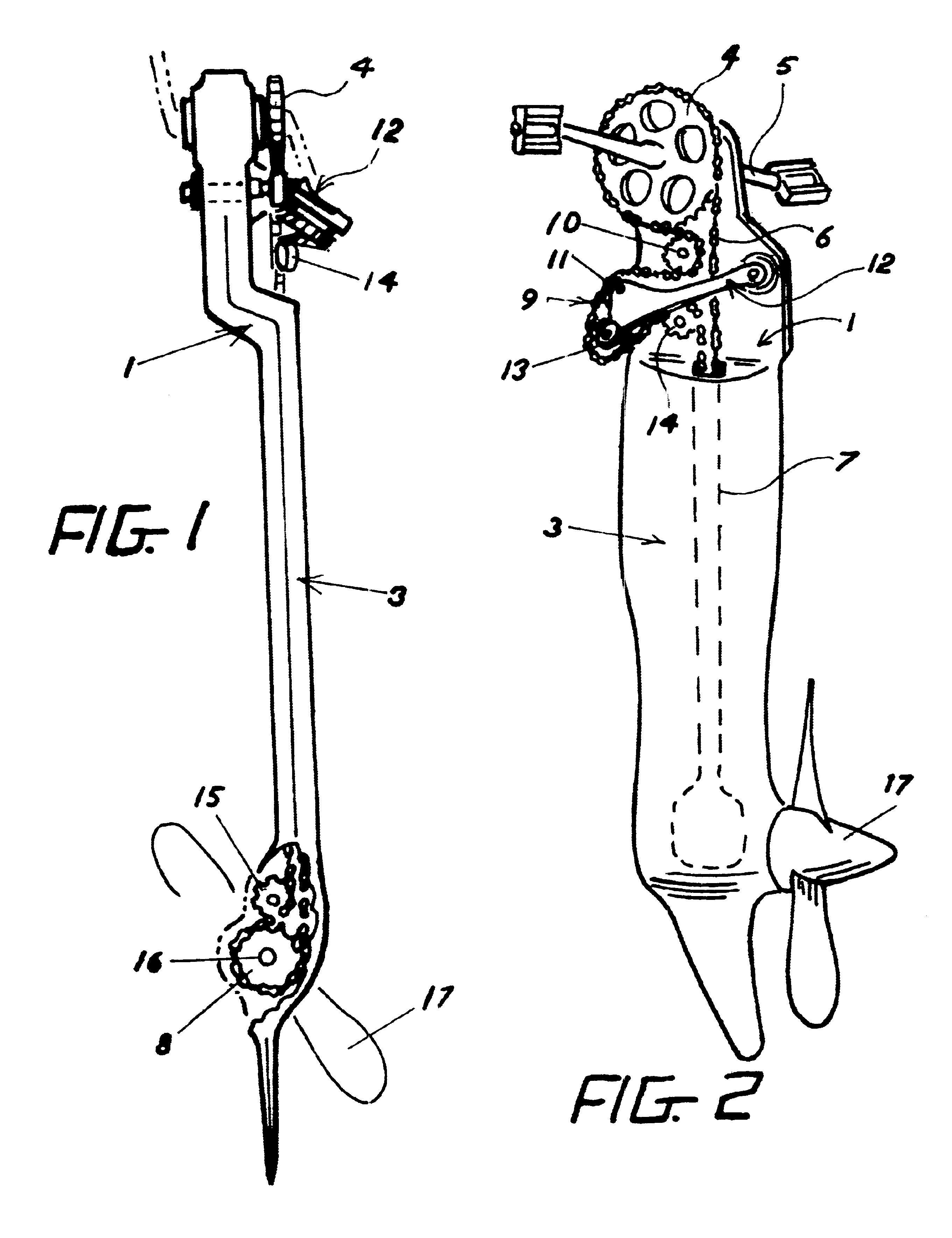
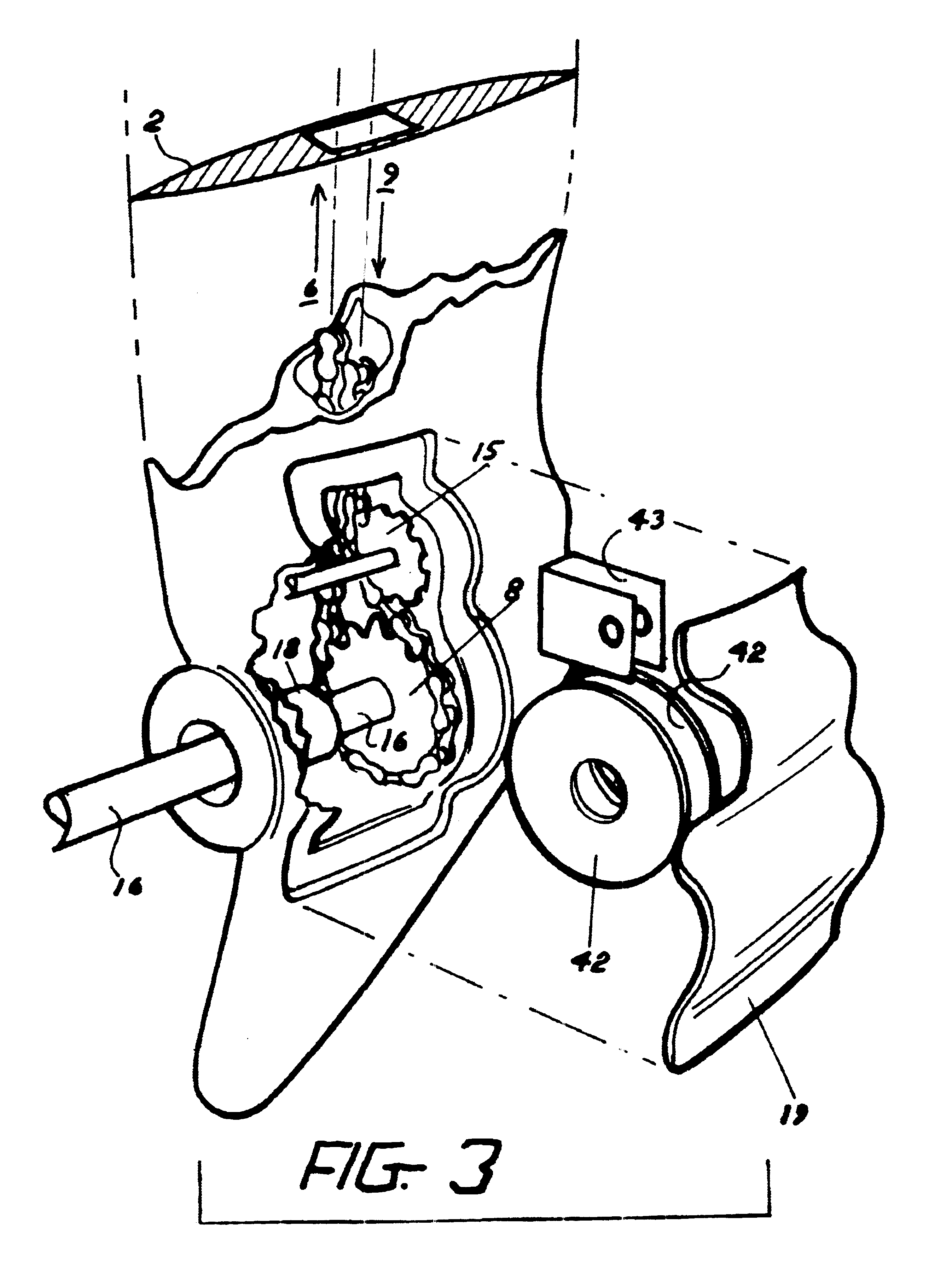
An alternative Embodiment for the tensioner arm 12 in [FIG. 15] is where there is one large diameter idler 44 in lieu of idlers 11 and 13, and said tensioner arm 12 has one lug on it's end to fit said chain adjusting means 45.

embodiment # 2

ALTERNATIVE EMBODIMENT #2

Another alternative embodiment of this drive mechanism is where the frame 1 is a trunk in [FIG. 16] which supports the components entirely externally. Upper positioning idler 10 is supported by upper positioning idler boss 46. Lower positioning idler 14 is supported by lower positioning idler boss 47. Tensioner arm is supported by tensioner arm boss 48. Drive sprocket adjustment sleeve 35 is supported by adjustment sleeve boss 49. Driven sprocket positioning idler 15 is supported by driven sprocket positioning idler boss 50. The propeller shaft 16 is substantially long, and is held in place by an also substantially long keeper tube 51 and supported by occasional bushings (not shown). Said shaft and keeper descends past the waterline 52 in a gradual manner wherein there is low water resistance and only slight angle from the horizontal. Said keeper tube 51 is connected to said trunk frame 1 by clamping collars 53.

embodiment # 3

ALTERNATIVE EMBODIMENT #3

Still another alternative embodiment consists of the frame and jacket 1 in [FIG. 17] entirely encapsulating the components such that the drive mechanism is waterproof. A drive shaft 54 is driven by taper-pinned-pedals 55, with the drive sprocket 4 affixed in center of said shaft 54. Said shaft 54 is supported by water-sealed bearings 56 which rest in grooves 57. A water sealed cap 66 mounts said bearings 56 in place while keeping the resulting parting line watertight. Access to the tensioner arm 12 and the rest of the upper components is kept watertight by waterproof access cover 58.


PUM


Abstract

A pedal driven aquatic propulsion system comprises a driven sprocket located substantially vertically beneath a drive sprocket. The planes of rotation of the drive and driven sprockets are disposed substantially at right angles to one another. An endless chain drive transmits power from the drive sprocket to the driven sprocket, operating in a twisting three-dimensional orientation as it loops around the sprockets. A pivoting, self tensioning idler arm is adjustably mounted on a frame that encloses the propulsion drive, and comprises an idler sprocket disposed in rotatable contact with the chain drive to maintain the chain under constant tension. The plane of rotation of the idler sprocket is tilted and offset from the planes of rotation of the drive and driven sprockets. The constantly tensioning system comprises a series of stationary and flying idlers aligned to the natural twist of the chain.

Description

STATEMENT REGARDING FEDERALLY SPONSORED RESEARCH AND DEVELOPMENTNot applicableIn inventing a propeller drive for a human powered boat, the initial impulse would be to use a rope or belt. Indeed, this approach has been picked up on in the development of human powered boat drive systems at least as far back as Victorian times as represented in 1869 with Ross (U.S. Pat. No. 98,302), 1889 with Frenzel (U.S. Pat. No. 397,282), as well as by others including Storms, (U.S. Pat. No. 621,465), Mosteller (U.S. Pat. No. 1,072,027), Szafka (U.S. Pat. No. 1,411,540), Avellino (U.S. Pat. No. 3,182,628), Shiraki (U.S. Pat. No. 5,194,024), Parant (U.S. Pat. No. 5,362,264), Avvocato (France 1,375,350), _Lackner (Germany 2,226,178) . The fact that even though a toothed belt may be used as in White (5,547,406 et el), Lekhtman (U.S. Pat. No. 6,231,408), Marinc (U.S. Pat. No. 5,580,288), et el, doesn't ease the condition of energy loss due to deforming soft material as it engages into and twists around ...

Claims


Application Information

Patent Timeline
Patent Type & Authority Patents(United States)
IPC IPC(8): B63H16/00B63H16/20
CPCB63H16/14B63H16/20B63H2016/202B63H2023/025
Inventor FREE, JAMES JACOB
Owner FREE JAMES JACOB
Why Eureka
Try Eureka