Calibration structure for circuit breakers having bimetallic trip member

a circuit breaker and trip member technology, applied in circuit breaker switches, relays, protective switch details, etc., to achieve the effects of improving durability, less sensitivity, and increasing performance repeatability

Inactive Publication Date: 2004-04-13
SENSATA TECH MASSACHUSETTS INC
View PDF11 Cites 43 Cited by
  • Summary
  • Abstract
  • Description
  • Claims
  • Application Information

AI Technical Summary

Benefits of technology

It is an object of the invention to provide a calibration assembly which has less sensitivity and one which enables increased performance repeatability. Another object of the invention is the provision of a circuit breaker having a calibration assembly which has improved durability. Another object is the provision of a circuit breaker which overcomes the prior art limitations noted above.
Briefly, in accordance with the invention, the calibration screw for the bimetallic member, also referred to as trip arm hereinafter, is placed in line with the top or second end of the trip arm. This provides one-to-one displacement for the screw to trip arm significantly reducing calibration sensitivity and increasing performance repeatability. According to a first embodiment, the trip arm of the actuator assembly is generally U-shaped with the free ends of the legs forming a first end of the trip arm. The free end of one leg is fixedly connected, as by welding, to a first end of a pivotable calibration base with a piece of insulation material, such as Kapton tape disposed about the free end of the second leg and then received in a clip portion of the calibration base bent back on itself to capture the leg. The calibration base is pivotably mounted in the housing of the circuit breaker and has a slotted second end aligned with and generally coextensive with the second end of the U-shaped trip arm, i.e., the bight or junction of the two legs with the trip arm disposed intermediate the calibration base and the motion transfer member. The calibration screw head is formed with a circumferentially extending groove which receives and captures the slotted end of the second end of the calibration head. Rotation of the calibration screw will cause pivoting movement of the actuator assembly toward or away from the motion transfer plate adjacent thereto.

Problems solved by technology

In the previously discussed calibration structure described in the patents, some additional calibration attempts are possible due to spring back of the second wall when the screw is turned out, limited by stress relief and the like.

Method used


Image

  • Calibration structure for circuit breakers having bimetallic trip member
  • Calibration structure for circuit breakers having bimetallic trip member
  • Calibration structure for circuit breakers having bimetallic trip member

Examples


Embodiment Construction

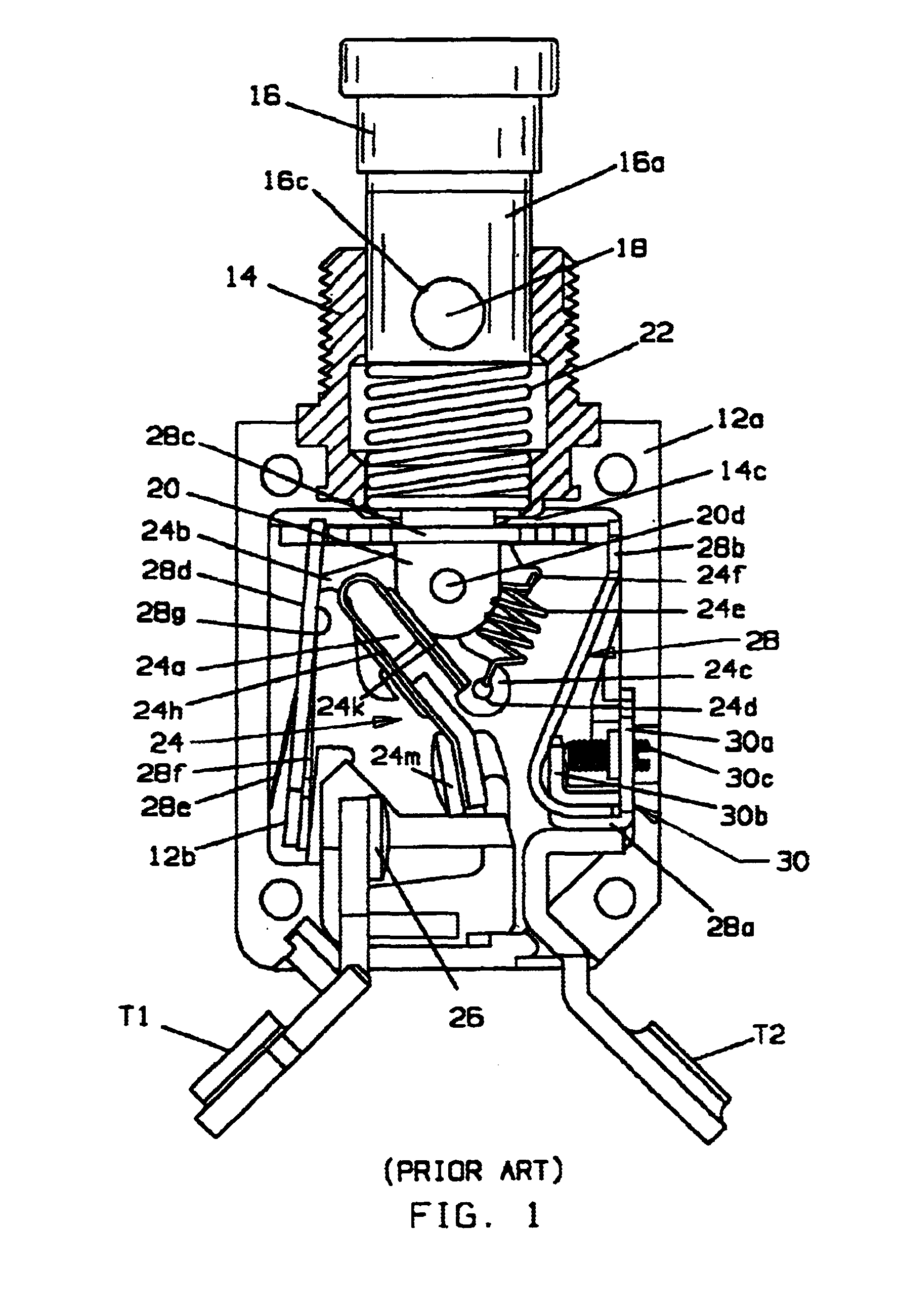
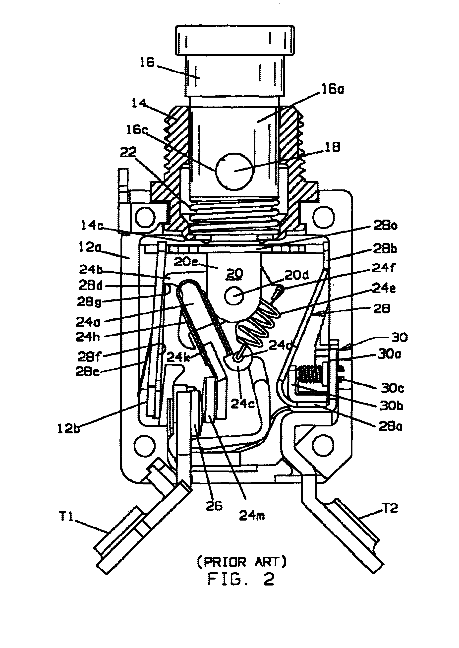
Turning to FIGS. 1 and 2 of the drawings, a circuit breaker of the type shown and described in U.S. Pat. No. 3,361,882referenced above, comprises a housing 12 having first and second case halves 12a, one being removed in the drawings for purposes of illustration, a mounting bushing 14, a pushbutton 16 slidably movable within the bore of bushing 14 between an open contacts position in which the top of the pushbutton extends outwardly beyond the open end of bushing 14 exposing a color coded cylindrical surface 16a providing visual indication of the open contacts position shown in FIG. 1 and a closed contacts position in which cylindrical surface 16a is disposed within bushing 14 as shown in FIG. 2.

Pushbutton 16 comprises a barrel portion having openings 16c in the wall thereof which receive latching balls 18. A plunger 20 is slidably received in the bore of barrel portion 16b and is provided with a circumferentially extending recess (not shown) having circumferentially extending angle...


PUM


Abstract

A thermally compensated circuit breaker has a movable contact assembly (24) which mounts a movable electrical contact (24m) for movement between open and closed contacts positions with a stationary electrical contact (26). The contacts are maintained in the closed circuits position by a latching mechanism (24b, 28g) which prevents opening of the contacts through an opening contacts force provided by a spring (24e). A current carrying trip arm (40a, 44a) deflects upon sufficient I.sup.2 R heating to transfer motion to the latch to separate the latch (24b) from the latch receiving catch (28g) to trip the circuit breaker. The trip arm (40a, 44a) is part of a pivotably mounted actuator assembly (40, 44) having a movable end portion spaced from the pivot disposed adjacent a motion transfer member (28c). A calibration screw (42a) is located so that the longitudinal axis is in line with a movable end portion of the actuator assembly and the motion transfer member. In one embodiment the head of the calibration screw is captured in a slot in the free end of a calibration base (42d) attached to the trip arm so that deflection of the trip arm directly transfers motion to the motion transfer member and in another embodiment the calibration screw head is captured in a slot in the free end of the trip arm so that a bowing deflection of the trip arm causes a calibration base (46) to which it is attached at an end thereof to rotate with the calibration base directly transferring motion to the motion transfer member.

Description

FIELD OF THE INVENTIONThis invention relates generally to thermostatic type circuit breakers used to interrupt an electrical circuit under selected overload conditions and more particularly to improvements in means for calibrating such circuit breakers.BACKGROUND OF THE INVENTIONTrip free, ambient compensated circuit breakers are well known. An example of this type of circuit breaker is disclosed and claimed in U.S. Pat. No. 3,361,882, assigned to the assignee of the present invention, the subject matter of which is incorporated herein by this reference. As described, the circuit breaker of this type has a movable contact assembly mounting a movable electrical contact for movement between open and closed contact positions with a stationary electrical contact. A latching mechanism is provided for maintaining the movable electrical contact in the closed contacts position against the bias of a contacts opening spring. An overload trip assembly includes a thermostatic actuator in the fo...

Claims


Application Information

Patent Timeline
Patent Type & Authority Patents(United States)
IPC IPC(8): H01H73/30H01H71/00H01H73/00H01H71/74
CPCH01H71/7427H01H73/30H01H2071/084
Inventor PELLON, CHRISTIAN V.PELLON, NICHOLAS V.BENTLEY, WILLIAM J.MORRISON, ERIC W.
Owner SENSATA TECH MASSACHUSETTS INC
Why Eureka
Try Eureka