Parameter estimator with dynamically variable search window size and/or placement

a dynamic search and estimator technology, applied in the field of parameter estimator with dynamic search window size and/or placement, can solve the problems of estimator typically exceeding available search time constraints, the detection of transmissions from multiple base stations or sectors is not generally effective,

Inactive Publication Date: 2004-05-18
QUALCOMM INC
View PDF7 Cites 30 Cited by
  • Summary
  • Abstract
  • Description
  • Claims
  • Application Information

AI Technical Summary

Benefits of technology

When the technique represented by any of these methods is applied to a group of signals during a search cycle, performance is improved compared to the performance using the default search window parameters provided by the network, since the size and / or placement of the search window which is used may be tailored to an individual signal based on a priori information regarding the signal. Therefore, search cycle time is reduced.

Problems solved by technology

However, such a detector is not generally effective for the purpose of detecting transmissions from multiple base stations or sectors since, unlike the search windows used for searching for GPS satellites, the search windows used for searching for base stations or sectors are determined by the network and are not optimized for position location technologies.
Consequently, the estimator will typically exceed available search time constraints if the size of the predetermined search window is set too large or the window is inappropriately placed.

Method used


Image

  • Parameter estimator with dynamically variable search window size and/or placement
  • Parameter estimator with dynamically variable search window size and/or placement
  • Parameter estimator with dynamically variable search window size and/or placement

Examples


second embodiment

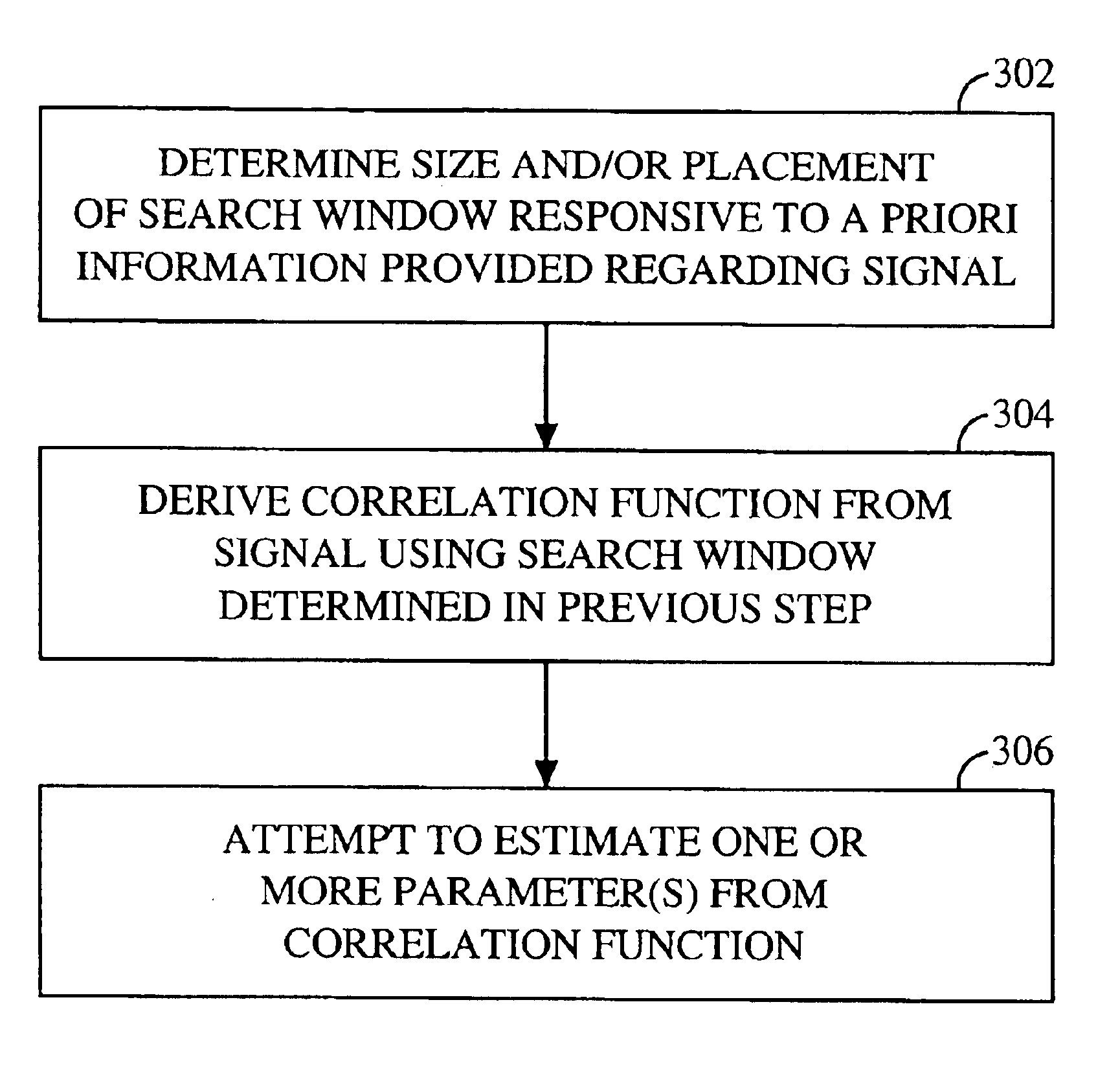
Referring to FIG. 3B, a flowchart of a method of estimating one or more parameter(s) of a signal using a dynamically variable search window is illustrated. The method begins with step 308, which comprises estimating one or more parameter(s) of a first signal from a correlation function derived using a first search window. The method proceeds to step 310, which comprises estimating one or more parameter(s) of a second signal from a correlation functions derived using a second search window which may differ or vary from the first. The second search window may have a smaller size than that of the first., and may also be differently positioned than the first, if, for example, a priori information is available for the second signal, but not the first, where the a priori information allows the estimator to roughly estimate a time of arrival of the second signal.

third embodiment

Referring to FIG. 3C, a method of estimating one or more parameter(s) of a signal using a dynamically variable search window is illustrated. This embodiment begins with step 312, which comprises attempting to estimate one or more parameter(s) of a signal from a correlation function derived using a first search window.

Step 312 is followed by step 314. In step 314, it is determined whether the estimation attempt 312 was successful or not. If so, the one or more parameter(s) may be recorded in a memory as indicated by optional step 318. If not, step 316 is performed. In step 316, a second attempt is made to estimate the one or more parameter(s) from a correlation function derived using a second search window which may differ from the first.

For example, if the first attempt was unsuccessful because a peak of the correlation function derived from the signal using the first search window could be detected but at an insufficient level of confidence, another attempt could be made to estimat...


PUM


Abstract

A parameter estimator for estimating one or more parameter(s) from a correlation function derived from a signal using a dynamically variable search window is described. The parameter estimator may be employed in a subscriber station to estimate the time of arrival of one or more base station pilot signals in a wireless communication system. This information may be utilized in an overall advanced forward link trilateration (AFLT) process for estimating the location of the subscriber station.

Description

This invention relates to the field of parameter estimation using correlation analysis, and more specifically, to a parameter estimator employing correlation analysis for estimating parameter(s) of signals subject to distortions caused by factors such as multi-path.RELATED ARTThe Global Positioning System (GPS) is a collection of satellites each of which travels in a precise orbit above the earth's surface. Each satellite transmits a signal modulated with a pseudo-noise (PN) code unique to the satellite. Each PN code comprises a predetermined number of chips. A GPS receiver receives a composite signal comprising a mixture of signals from each of the satellites that are visible to the receiver. A signal estimator in the receiver detects a transmission from a particular satellite by determining the degree of correlation between the received signal and shifted versions of the PN code for that satellite. If a peak of sufficient quality in the correlation value for one of the shift offse...

Claims


Application Information

Patent Timeline
Patent Type & Authority Patents(United States)
IPC IPC(8): G01S5/02H04B1/707G01S19/09G01S19/46H04B1/7075
CPCG01S5/0221H04B1/70754H04B1/709
Inventor RICK, ROLAND R.RISTIC, BORISLAVAMERGA, MESSAYSTEIN, JEREMY M.FERNANDEZ-CORBATON, IVANBHATIA, ASHOK
Owner QUALCOMM INC
Why Eureka
Try Eureka