Infiltration and gas recovery systems for landfill bioreactors

a bioreactor and gas recovery technology, applied in the trench field, can solve the problems of difficult installation, high cost, and troublesome disposal and odor

Inactive Publication Date: 2004-06-01
WASTE MANAGEMENT INC
View PDF16 Cites 30 Cited by
  • Summary
  • Abstract
  • Description
  • Claims
  • Application Information

AI Technical Summary

Problems solved by technology

Landfill leachate--the aqueous solution that accumulates at the bottom of landfills also poses disposal and odor problems.
The combination of leachate recirculation and gas extraction of landfill has created a problem with gas extraction well flooding and fouling.
This requirement for both vertical and horizontal piping in the landfill makes installation difficult and expensive.

Method used


Image

  • Infiltration and gas recovery systems for landfill bioreactors
  • Infiltration and gas recovery systems for landfill bioreactors
  • Infiltration and gas recovery systems for landfill bioreactors

Examples


Embodiment Construction

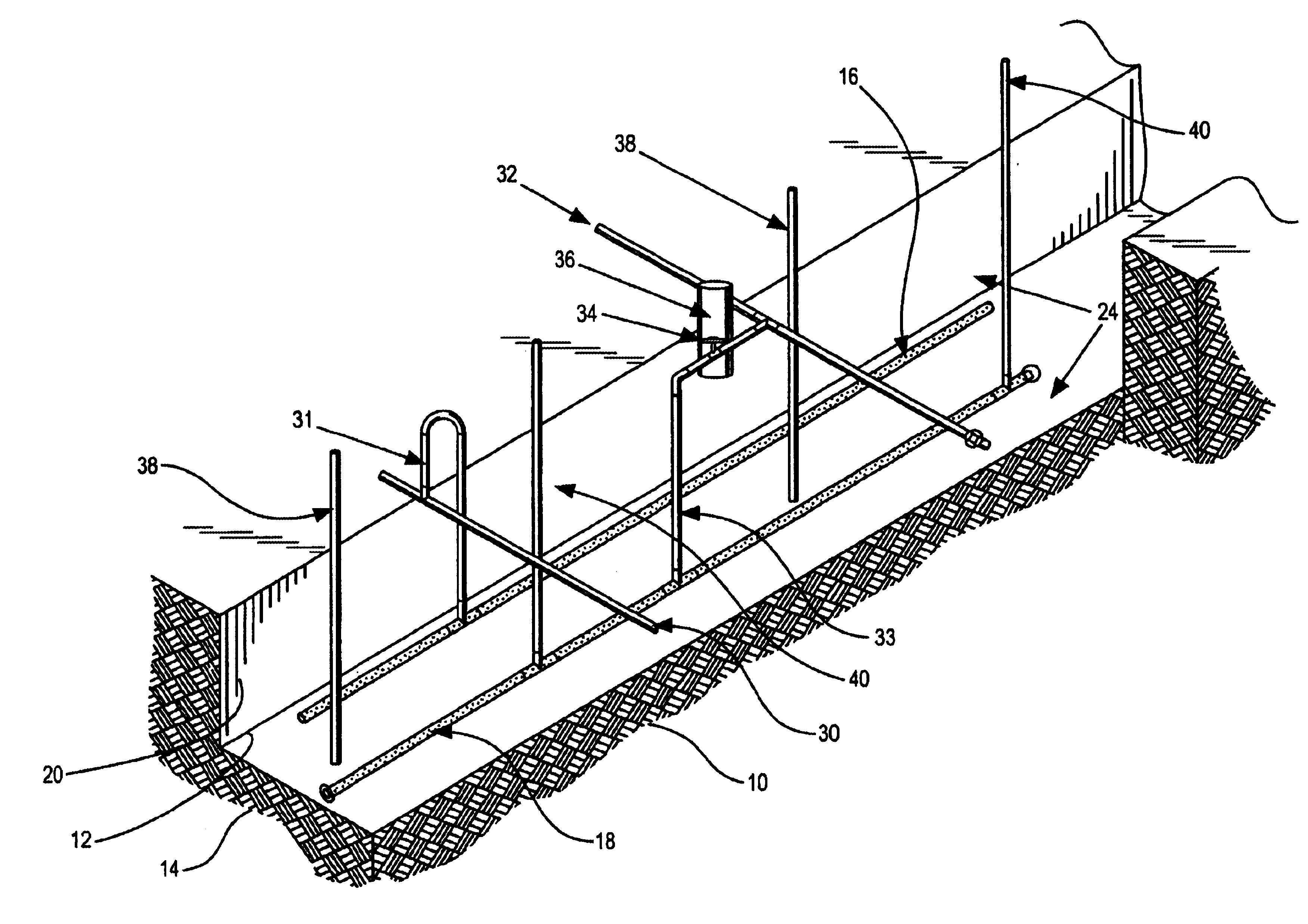
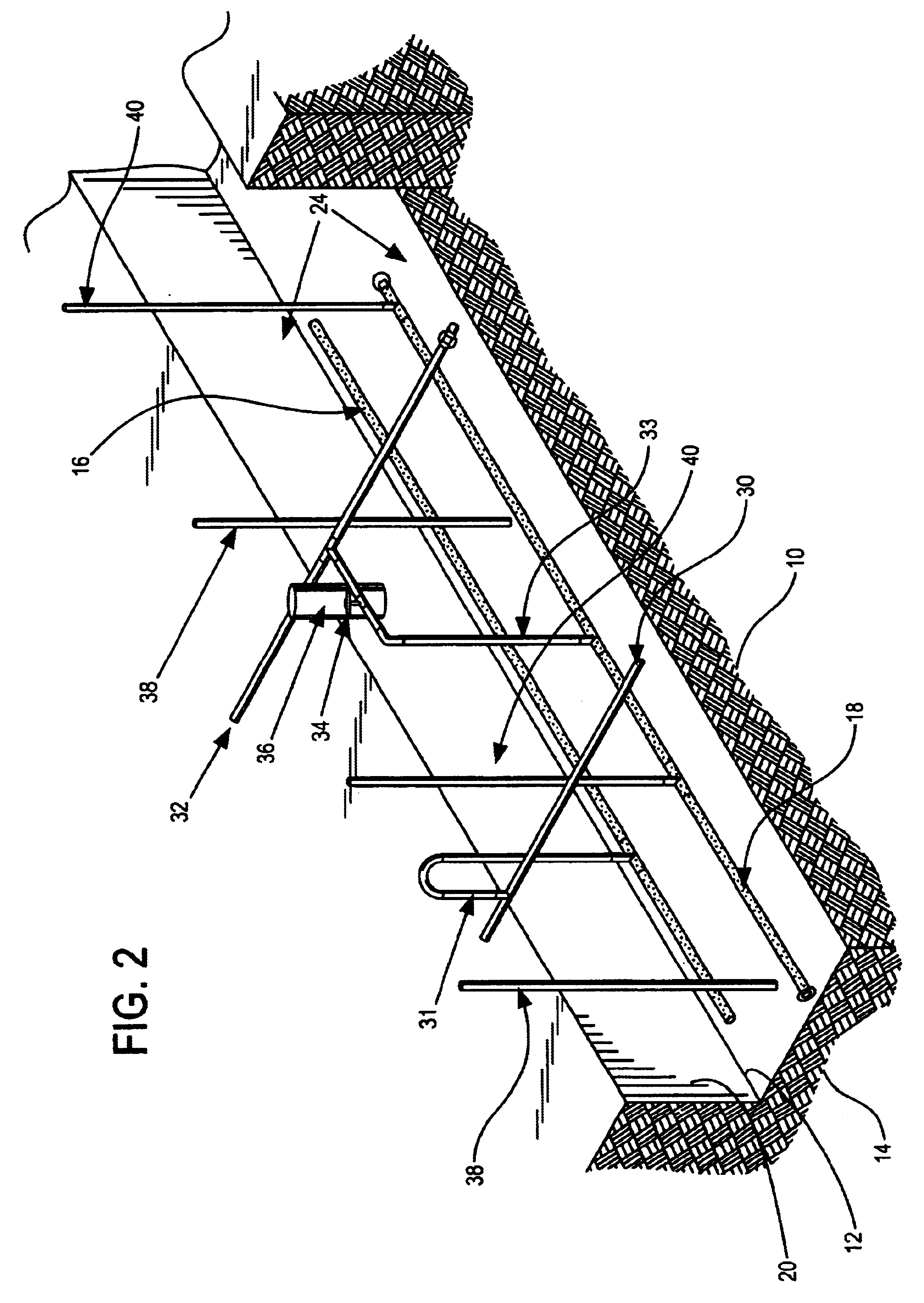
The present invention includes a landfill including a moisture infiltration piping system in combination with horizontal gas extraction piping system as well as to methods for installing the piping systems in a landfill.

As used herein the term "liquid" refers to any source of water including landfill leachate, fresh water, waste water of any kind, and any combinations thereof.

The term "horizontal" when used in conjunction with a description of a liquid distribution pipe a or a gas collection pipe refers to piping that may be placed on a grade from 0 to 10.degree. from horizontal. The term horizontal does not require that the piping be precisely horizontal. Deviation from a horizontal orientation is also anticipated based upon variations it the landfill slope trench construction.

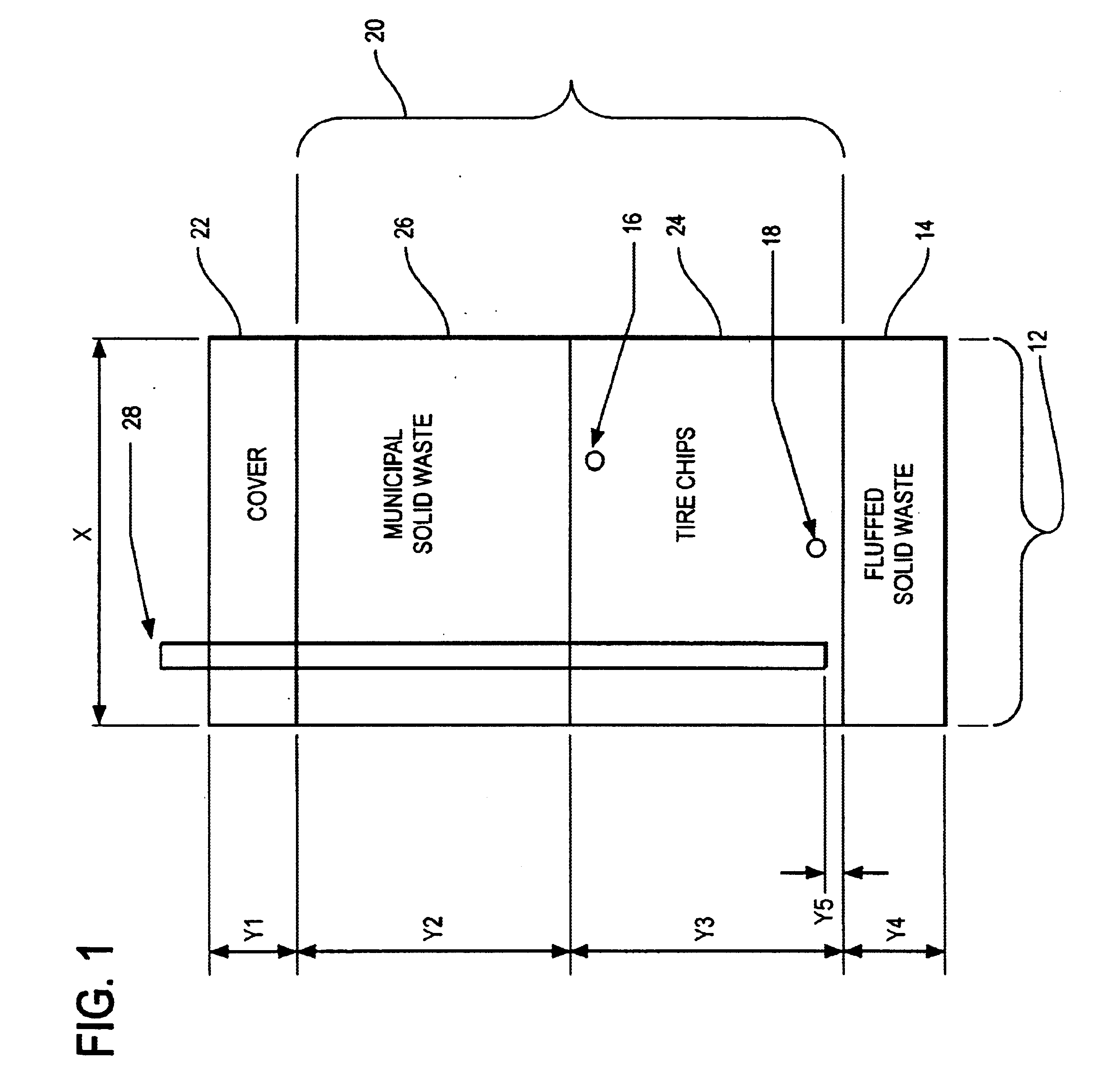
Liquid will typically be applied to the landfill on a continuous or an intermittent basis in order to maintain the landfill moisture content in a range of about 35 wt % and preferably to at least 55 wt %. In ...


PUM


Abstract

A trench located in a landfill including the combination of a liquid infiltration piping system and a horizontal gas withdrawal piping system, the combination allowing for simultaneous liquid infiltration and gas withdrawal from a landfill.

Description

(1) Field of the InventionThis invention concerns a trench located in a landfill including the combination of a liquid infiltration piping system and a horizontal gas withdrawal piping system that allows for simultaneous liquid infiltration and gas withdrawal. The trench of this invention can be retrofit into existing landfills or they can be incorporated into landfills as the landfill is being constructed.(2) Description of the ArtThe recovery of landfill gases including light hydrocarbons such as methane has become commonplace and is regulated under New Source Pollution Standards (NSPS). It used to be common to burn gasses vented from landfill. However, it is becoming more common to use landfill gases to generate heat and or electricity.Landfill leachate--the aqueous solution that accumulates at the bottom of landfills also poses disposal and odor problems. One method for dealing with leachate odor problems that is gaining wide acceptance is to pump the leachate from the bottom to...

Claims


Application Information

Patent Timeline
Patent Type & Authority Patents(United States)
IPC IPC(8): B09B1/00B09B3/00
CPCB09B1/00B09B3/00Y02W30/30
Inventor HATER, GARYBARBUSH, JOHN A.BARR, RICHARD N.
Owner WASTE MANAGEMENT INC
Why Eureka
Try Eureka