Sleeve for flexographic printing

a flexographic printing and flexographic printing technology, applied in office printing, printing, printing processes, etc., can solve the problems of dangerous discharge into the ink duct, the inability to ignore the problem of electrostatic charging even in the printing presses for flexographic printing, and the inability to ignite or deflagrate the solvents in the colors

Inactive Publication Date: 2004-06-08
POLYWEST KUNST SAUERSSIG & PARTNER
View PDF12 Cites 7 Cited by
  • Summary
  • Abstract
  • Description
  • Claims
  • Application Information

AI Technical Summary

Benefits of technology

A sleeve completely made out of CFRP is mountable only in thin wall thicknesses of up to about 5 mm. For thicker wall thicknesses, the sleeve body is normally provided with at least one layer of non-conductive, compressible material in order to ensure the size of the sleeve for the mounting or dismounting. For such sleeves, it is provided according to the present invention for the layer made of non-conductive material to be penetrated by the element for diverting electrostatic charges. In the preferred embodiment of a sleeve with a non-conductive, cylindrical layer or interlayer, the element is provided in a radially extending recess in the sleeve body. The recess may be formed by a radial borehole, in particular. So that the diverting element for the electrostatic charging does not hinder the compressibility of the layer made of a non-conductive material, it is particularly favorable in this embodiment if the element may change its length in radial direction, and after the mounting, independently adjusts to the length necessary for the electrical connection. This may preferably be achieved by having the element exhibit a spring-loaded contact body. It is particularly advantageous if the contact body is arranged in such a way that it juts out beyond the inside of the sleeve body before the mounting. Using the spring, the contact body is therefore preloaded towards the inside of the sleeve, or pressed in the mounting state against the outer wall of the roll of the king roll, thereby ensuring the electroconductive connection between the conductive surface of the sleeve and the electroconductive king roll. In order to facilitate the assembly of the sleeve and prevent obstructions to the lifting motion at the element, it is advantageous if the contact body is formed by a ball or at least exhibits a spherical contact end.
In order to able to install the element in sleeves in a simple manner, it may exhibit an electroconductive housing, e.g., made of metal, which contains the spring and the contact body, and with its housing bottom, is connected to the conductive surface. As set forth at the start, already existing sleeves or sleeve bodies may subsequently be made conductive. For this purpose, a sleeve body made of non-conductive material, in particular, may subsequently be provided with at least one radial through-bore hole, into which an element is inserted for electrostatic diversion before the conductive surface is applied. The element may, in particular, be screwed or glued in place into the through-bore or the recess. It is furthermore favorable if the recess or through-bore is countersunk on the inside of the sleeve body so that the air cushion occurring between the inside of the sleeve body and the king roll during the mounting or dismounting of the sleeve may not result in a displacement or loosening of the element or its housing.
The contact zone need not inevitably lie on the inside of the sleeve. Most king rolls are provided with a centering overhang for the register adjustment, with the sleeve using the centering overhang to center itself with a centering recess during the mounting. In such king rolls, the contact zone may thus be a component of the centering recess, resulting in the further advantage that the compressibility of the interlayer is not affected. In order to ensure the contact of the contact zone with the centering overhang, spring-loaded contact elements may be provided in the centering recess.

Problems solved by technology

Among experts, it was previously assumed that in flexographic printing, because of the small number of printing couples, the problem of electrostatic charging is negligible, and even in combustible solvents, such as alcohols, glycol or carboxylic acid ester used in flexographic printing, an ignition or deflagration of the solvents in the colors is not expected.
However, because of higher demands on work safety and the need for flexographic printing presses with a greater number of printing couples, the problem of electrostatic charging even in printing presses for flexographic printing can no longer be ignored.
For instance, they may occur between the substrate to be printed on, such as a foil, and the printing block, because of the lifting motion and because of excessive charging of the dye.
If suitable protective measures are not met, as the number of printing couples increase, the electrostatic charges increase as the substrate to be printed on advances in the machine, so that dangerous discharges into the ink ducts or into the chamber color ductor may occur in the rear printing couples as seen from the direction of processing.

Method used


Image

  • Sleeve for flexographic printing
  • Sleeve for flexographic printing

Examples


Embodiment Construction

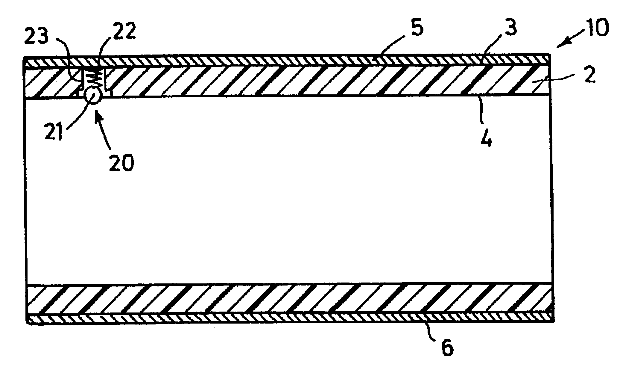
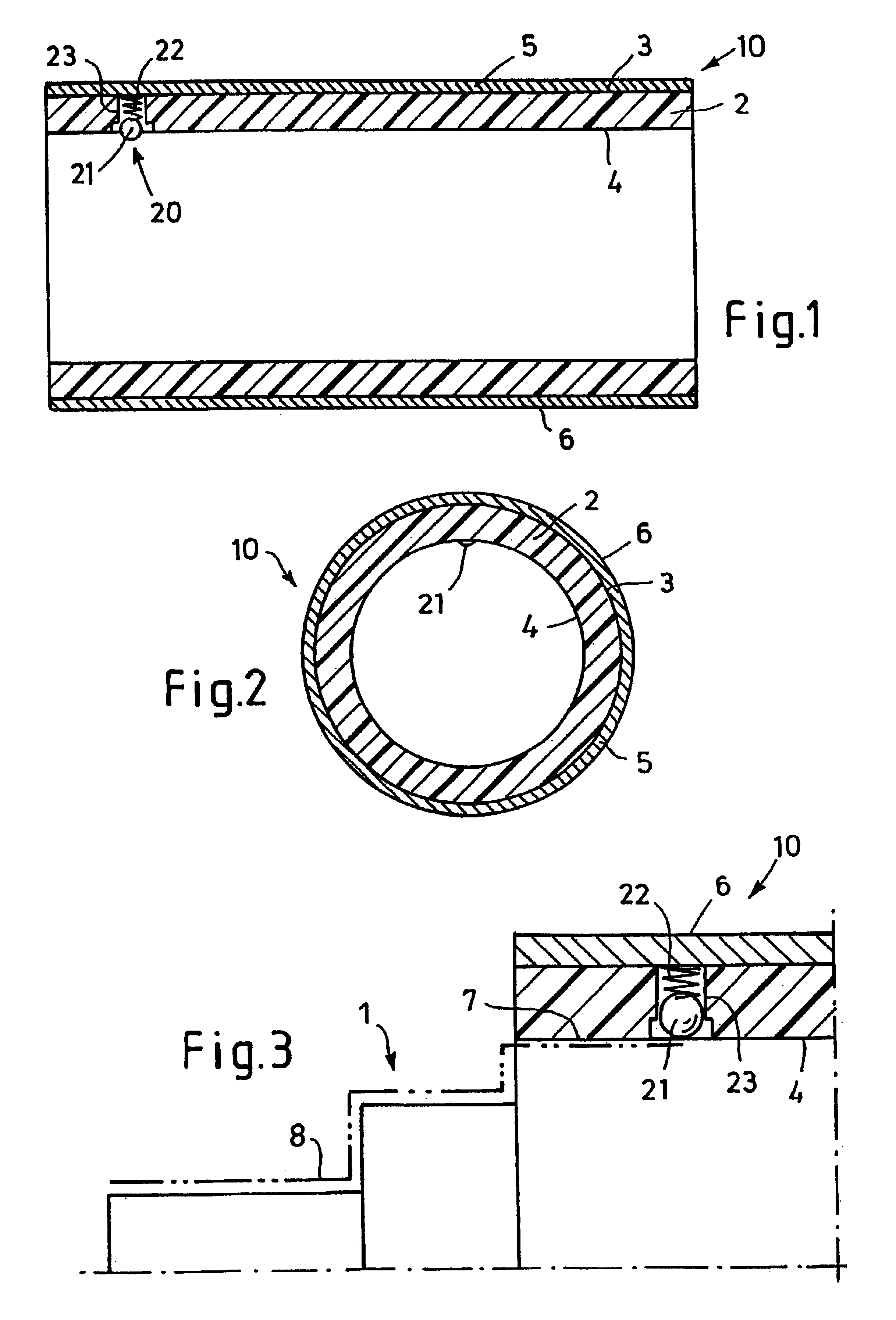
In the figures, reference number 10 indicates a sleeve for the flexographic printing, which is mountable on a flexographic printing press--not shown further--according to the air-cushion principle, on a king roll 1 designed as an air cylinder, shown exclusively in FIG. 3. Sleeve 10 has a cylindrical sleeve body 2 with a multi-layer structure. Sleeve 10 may, in particular, be a so-called build-up sleeve. Sleeve body 10 may exhibit a base sleeve made of a glass fiber reinforced plastic, for example, which is provided with several layers, such as compressible flexible foam, LD casting compound, high-resistance foam, and a hard coat or soft coat outer layer. The type and fastening of the printing blocks, used for printing and which is not shown, then depend on the outer layer selected.

In the embodiment shown, sleeve body 2 is made either completely out of a non-electroconductive material, or sleeve body 2 exhibits a continuous interlayer made of a non-electroconductive material, which p...


PUM


Abstract

A sleeve (10) for flexographic printing includes a sleeve body (2) made of an at least partially non-electroconductive material, which within its inside (4) is mountable on an electroconductive king roll on the outer wall of the roll, of a printing press, the king roll being designed as an air cylinder, and exhibiting at least one contact zone with the king roll. The sleeve exhibits an electroconductive surface (6), which is connected to the contact zone via at least one electroconductive element (20) provided in the sleeve body (2) for diverting electrostatic charges into the outer wall of the roll of the king roll. The sleeve is therefore given an electroconductive structure, through which the unavoidable electrostatic charges in printing presses with a plurality of printing couples are diverted via the king roll before it reaches a scale that would suffice for a discharge, ignition, or deflagration of the solvents used in the printing.

Description

BACKGROUND OF INVENTIONThe invention relates to a sleeve for flexographic printing, having a sleeve body made of an at least partially non-electroconductive material, which is mountable with its inside on an electroconductive king roll of a printing press designed as an air cylinder, and which in the assembly state exhibits at least one contact zone with the king roll.When printing foils, paper sheets, paper pages, and other substrates, the use of so-called sleeves (working sleeves), which are mounted on king rolls of printing presses using an air cushion and which hold the printing block, made of rubber or other elastic synthetic photopolymer, for a subsequent printing process, has increasingly been gaining acceptance. The king rolls of the printing presses, which are almost without exception made of steel cylinders, are for this purpose provided with an internal air system leading to bore holes on the outer wall of the roll, which are impinged on with compressed air when the sleev...

Claims


Application Information

Patent Timeline
Patent Type & Authority Patents(United States)
IPC IPC(8): B41C1/00B41F5/00B41C1/18B41F5/24B41F27/00B41F27/10B41F30/00B41N7/00B41N1/00B41N1/16B41F13/08B41N1/22
CPCB41C1/182B41F5/24B41F27/105B41F30/00B41C1/18B41N1/16B41N7/00B41P2200/12B41N2207/02
Inventor LORIG, HEINZLORIG, STEPHAN
Owner POLYWEST KUNST SAUERSSIG & PARTNER
Why Eureka
Try Eureka