Semiconductor integrated circuit device and delay-locked loop device

a technology of integrated circuit and delaylock, which is applied in the direction of pulse automatic control, static storage, instruments, etc., can solve the problems of increased power consumption, hazard or abnormal pulses, and difficulty in maintaining high timing precision, so as to prevent deviation in output timing and reduce power consumption

Inactive Publication Date: 2004-06-15
PS4 LUXCO SARL
View PDF6 Cites 60 Cited by
  • Summary
  • Abstract
  • Description
  • Claims
  • Application Information

AI Technical Summary

Benefits of technology

In addition, a DDR-II-SDRAM is provided with four delay lines, so that the delay-line operating current is four times the delay-line current of a DDR-I-SDRAM. The result is an increase in power consumption.
Accordingly, it is an object of the present invention to provide a DLL and a semiconductor integrated circuit device of reduced power consumption suited for use in equipment that complies with DDR-II specifications.
Another object of the present invention is to provide a DLL and a semiconductor integrated circuit device in which the occurrence of hazards at the time of tap changeover is suppressed, thereby preventing a deviation in output timing as well as malfunction.

Problems solved by technology

This makes it difficult to maintain a high timing precision.
The result is an increase in power consumption.
If the tap is changed over at the timing at which the signal that propagates through the interior of the delay line is output from the tap, a hazard or abnormal pulse may be produced in the data-output clock signal CLKOE or a malfunction may occur.

Method used


Image

  • Semiconductor integrated circuit device and delay-locked loop device
  • Semiconductor integrated circuit device and delay-locked loop device
  • Semiconductor integrated circuit device and delay-locked loop device

Examples


first embodiment

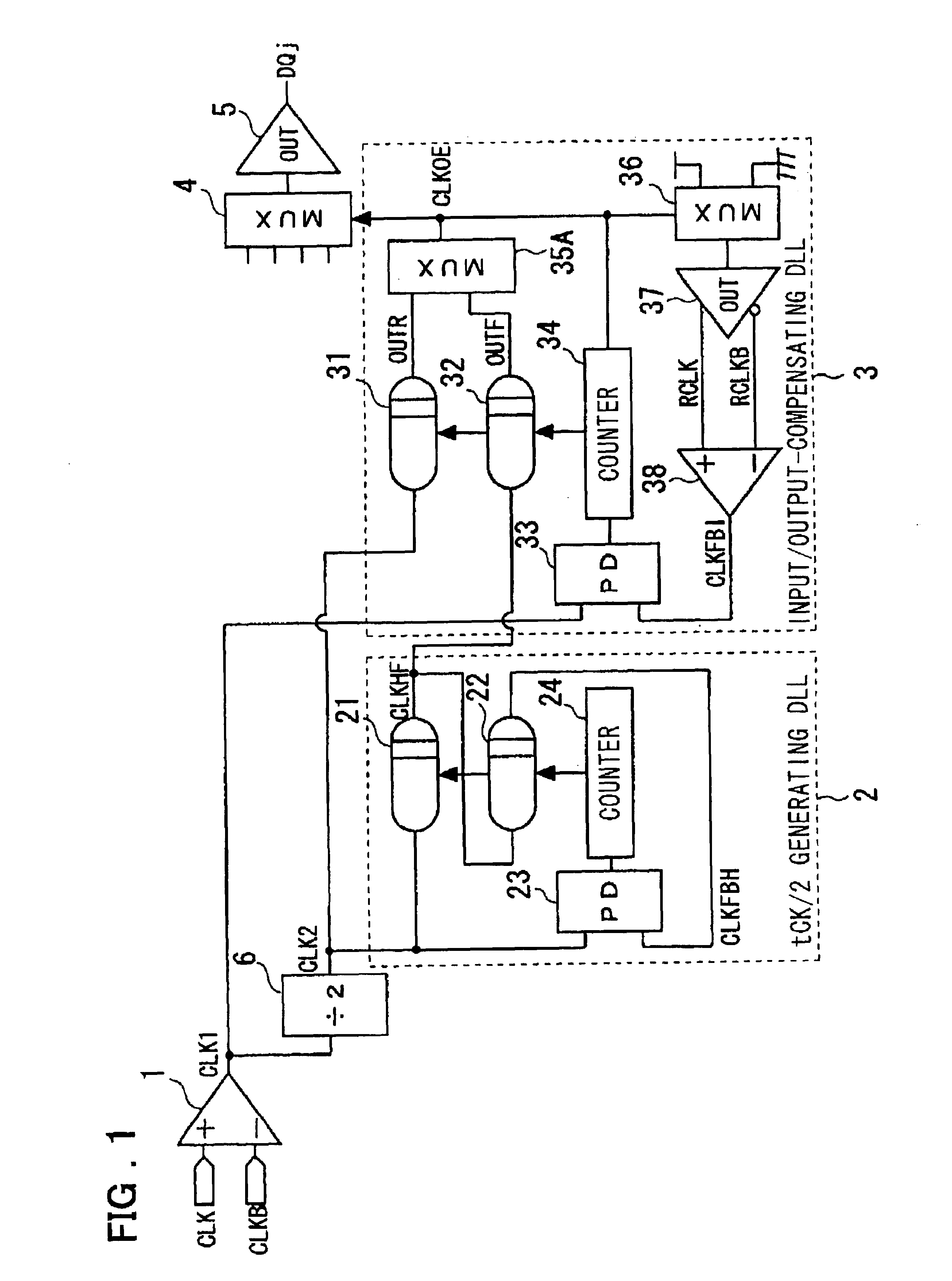
In the present invention, as shown in FIG. 1, a delay-locked loop (2) for a DCC function is so adapted that the delay times of serially connected first and second delay lines (21, 22) are adjusted in such a manner that a signal obtained by delaying an input signal by the first and second delay lines (21, 22) will be in phase with the input signal, as a result of which the first delay line (21) outputs a signal obtained by delaying the input signal by one half cycle of the input signal. The delay-locked loop (2) is provided with a frequency dividing circuit (6) for performing frequency-division of the input signal, and includes first delay adjusting means (23, 24) for delaying the output signal from the frequency dividing circuit (6) by the first and second delay lines (21, 22) and adjusting the delay times of the first and second delay lines (21, 22) in such a manner that the output signal of the frequency dividing circuit (6) and the output signal of the second delay line (22) will...

second embodiment

the present invention will now be described with reference to FIG. 3, which illustrates the structure of the second embodiment.

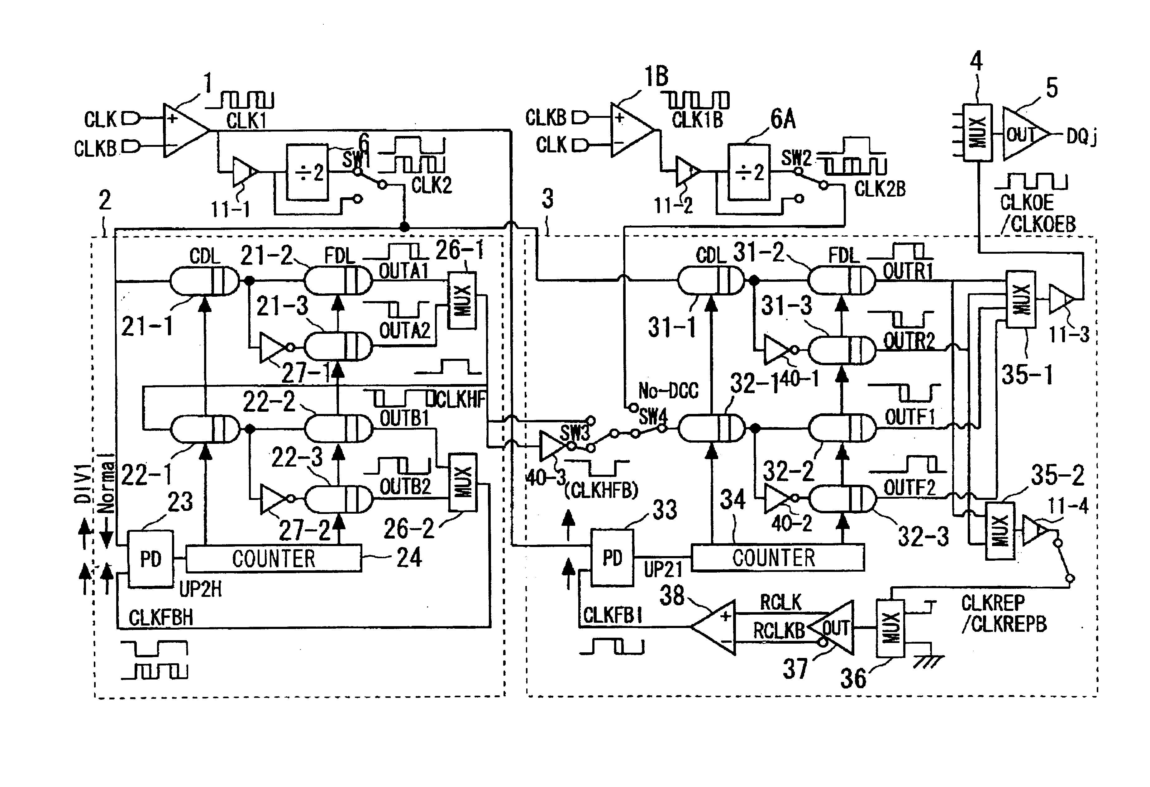
According to this embodiment, as shown in FIG. 3, the clock obtained by halving the frequency of the input clock signal CLK1 by the frequency dividing circuit 6 or the clock signal CLK1 (undivided) can be employed in the tCK / 2 generating DLL 2 by switching between these clocks using a switch SW1. Similarly, the clock signal obtained by halving the frequency of an input clock CLK1B (the complementary signal of the clock CLK1) by a frequency dividing circuit 6A or the clock signal CLK1B (undivided) can be employed in the input / output-compensated DLL 3 by switching between these clocks using a switch SW2. Further, a switch SW4 makes it possible to select a connection in such a manner that the duty correction (DCC) function is not introduced. Aspects of the second embodiment that differ from those of first embodiment shown in FIG. 1 will be described below.

The d...

third embodiment

the present invention will now be described with reference to FIG. 5, which illustrates the structure of the third embodiment. As shown in FIG. 5, this embodiment is obtained by providing the arrangement of FIG. 20 with latch circuits (aligners) 25, and 39 for latching the tap selection signals from the counters 24, and 34, respectively.

The tCK / 2 generating DLL, here designated by a reference numeral 2', is so adapted that the aligner 25 latches the tap selection signal from counter 24 at the rising edge of the output signal CLKHF of delay line 21. According to this embodiment, the latch timing of the aligner 25 is important. By using the rising edge of the output signal CLKHF of delay line 21 for this timing, the tap changeover operation is rendered hazard-free.

The aligner 25 latches the tap selection signal from the counter 24 at the rising edge of the signal CLKHF, and the taps of the delay lines 21 and 22 are changed over by the latched signal. As a result, a hazard of the kind ...


PUM


Abstract

The present invention provides a DLL and a semiconductor integrated circuit device of reduced power consumption suited for use in equipment that complies with DDR-II specifications. It also provides a DLL and a semiconductor integrated circuit device in which the occurrence of hazards at the time of tap changeover is suppressed, thereby preventing a deviation in output timing as well as malfunction. In accordance with one aspect of the present invention, a delay-locked loop device is provided for adjusting delay times of serially connected first and second delay lines in such a manner that a signal obtained by delaying an input signal by the first and second delay lines is in phase with the input signal, thereby outputting, from the first delay line, a signal that is the result of delaying the input signal by one half cycle of the input signal.

Description

This invention relates to a semiconductor integrated circuit device and, more particularly, to a delay-locked loop (DLL) and a semiconductor integrated circuit device equipped with the DLL.A DDR (Double Data Rate)-I-SDRAM (Synchronous Dynamic Random-Access Memory) is designed to perform data transfer at a transfer rate of 200 to 300 Mbps (megabits per second) with respect to an input clock having a frequency of 100 to 166 MHz. Design specification is such that data input is synchronized to both rising and falling edges of an input clock signal. The desired specifications can be achieved with a DLL of minimal structure by passing the entered clock through a single delay line as is.FIG. 18 is a diagram illustrating an example of a DLL(Delay Locked Loop) in compliance with DDR specifications, and FIG. 19 is a diagram illustrating the timing operation of this DLL.Referring to FIG. 18, the DLL 3A is equipped with an input buffer 1, the inputs to which are mutually complementary clock sig...

Claims


Application Information

Patent Timeline
Patent Type & Authority Patents(United States)
IPC IPC(8): G11C7/22G11C7/00G11C11/4076G11C11/407G06F1/10H03K5/00H03K5/13H03L7/08H03L7/081
CPCG11C7/1066G11C7/22G11C7/222G11C11/4076H03L7/08
Inventor TAKAI, YASUHIRO
Owner PS4 LUXCO SARL
Why Eureka
Try Eureka