Unfortunately, as
channel spacing decreases, each channel suffers from higher levels of performance degradation due to multi-channel operation. Specifically, the superposition of
harmonics results in significant detrimental effects on
data integrity within a specific channel. More particularly, in an optical
transmission system, densely packed channels exhibit an
intermodulation product, known as "four-wave mixing". Basically, the degradation from the
intermodulation product arises from sidebands being superpositioned on or about adjacent optical channels, with each
sideband generated as a consequence of the spacing between adjacent channels. Increasing the channel separation therefore improves transmitted
signal integrity, but this
improved performance only results from sacrificing overall transmission capacity.
One way to maintain the same total number of channels in a bidirectional
amplifier, whilst reducing the channel degradation arising from an
intermodulation product is to adopt an interleaved channel plan in which adjacent channels propagate in opposite directions. In practice, this means that the
channel spacing between adjacent channels in one direction has been doubled, with the effects on adjacent co-propagating channels accordingly reduced. An additional
advantage of this scheme arises from the distribution of the "
dead band" in which channels cannot be used. Specifically, in relation to a dual band
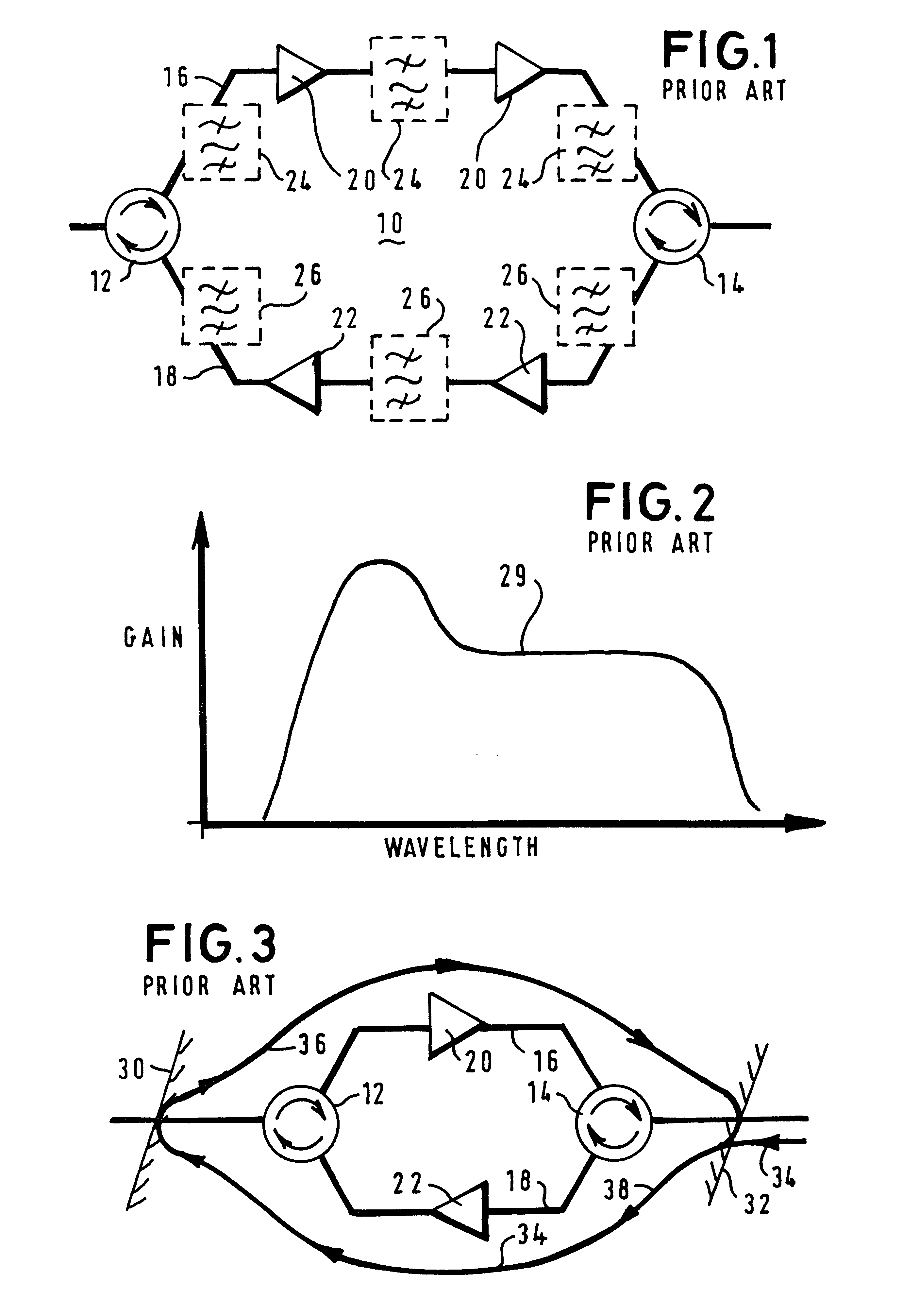
system in which distinct bands are allocated for up-link and down-link transmissions, it is imperative that the bands be separated, (isolated) to prevent corruption of data. Unfortunately, in any attenuated system (as implemented within a filter, for example) isolation is dependent on operating parameters of the actual attenuation devices. In the specific case of filters in an optical system, the filters have a response curve that gradually rises and gradually tails off. Consequently, a minimum
extinction zone must exist between the separate channel bands, with the width of the
extinction zone necessarily excluding any overlap potentially arising from the lead-in or
tail-off profiles of the filter
response characteristics. In other words, the
rate of increase of attenuation against
wavelength (termed "roll-off") that is achievable between the channel bands through filtering produces a portion of the bandwidth that cannot be used for communication information; this is the overlapping region of the "
dead band". In an interleaved case, the channel spacing in one direction is doubled and so the filter edges are steep enough not to lose a channel slot due to dead bands. Indeed, in practice, the
dead band is distributed across the whole of the operating bandwidth, and so the optical system is able to increase the total number of available channels.
EP-A-0 668 675 describes a multi-channel optical fibre communication system in which
wavelength division multiplexed channels have simple channel-to-channel spacing which prevent substantial
coincidence of 4-wave mixing products with channel carriers.
In a further aspect of the present invention there is provided an optical fibre supporting
bidirectional communication on a multiplicity of optical channels having adjacent wavelengths, the multiplicity of optical channels distributed between an up-link and a down-link, the optical fibre supporting at least one pair of channels having adjacent wavelengths in at least one of the up-link and the down-link, wherein channels assigned to the up-link and down-link are mutually exclusive and each of the up-link and the down-link comprises at least one other optical channel having a wavelength not adjacent to said at least one pair of channels, whereby four-wave mixing in each of an up-link and a down-link is reduced.
In still yet another aspect of the present invention there is provided a method of bidirectional transfer of data through an optical fibre, the data conveyed in up-link and down-link directions in the optical fibre in a multiplicity of optical channels having adjacent wavelengths, the multiplicity of optical channels distributed between the up-link and the down-link directions, the method characterised by the steps of: assigning at least one pair of channels having adjacent wavelengths to at least one of the up-link and the down-link, wherein channels assigned to the up-link and down-link directions are mutually exclusive and each of the up-link and the down-link directions comprises at least one other optical channel having a wavelength not adjacent to said at least one pair of channels, whereby four-wave mixing in each of the up-link and down-link directions is reduced; and modulating channels to support simultaneous transfer of the data in the up-link and down-link directions.
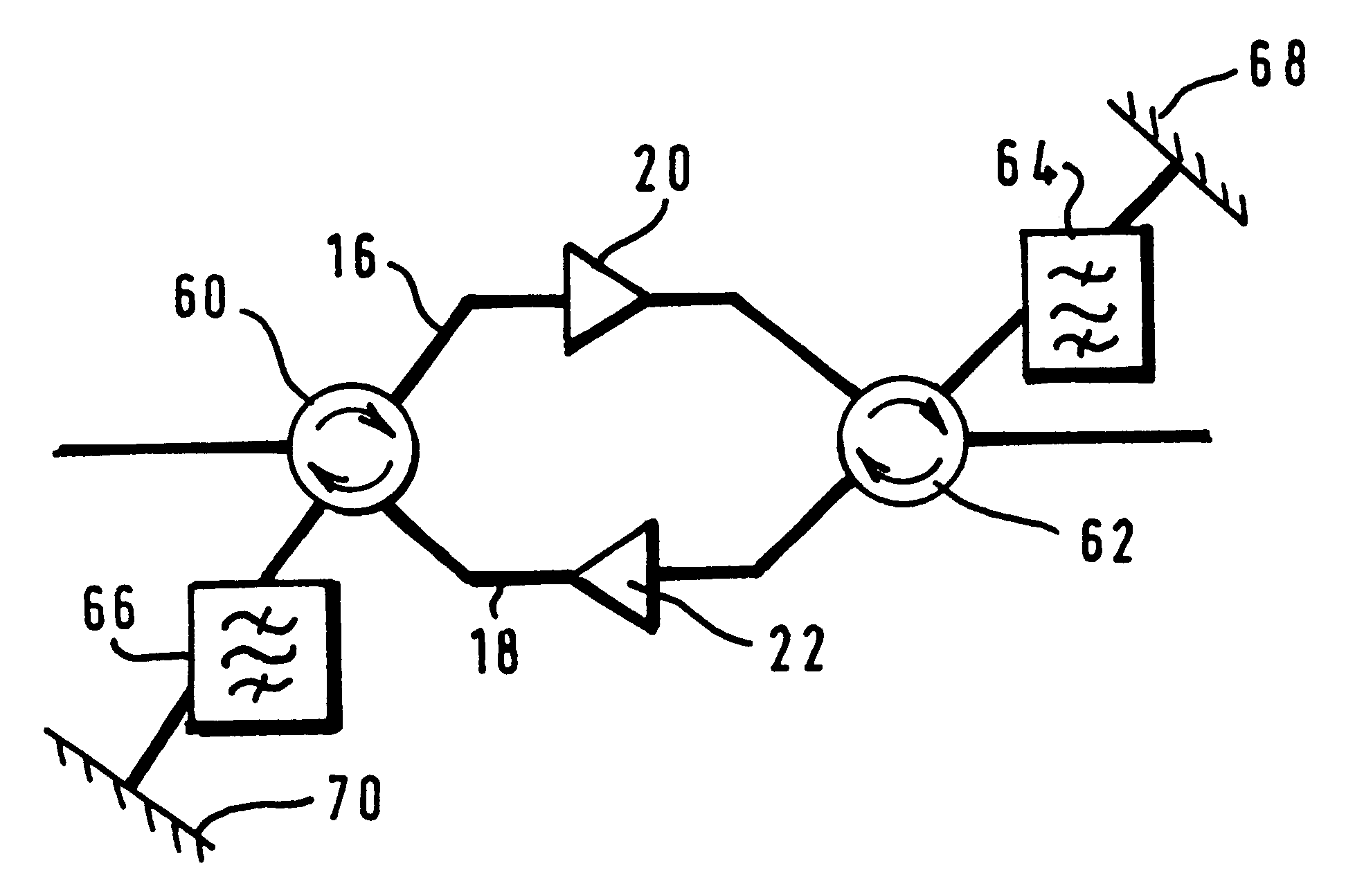
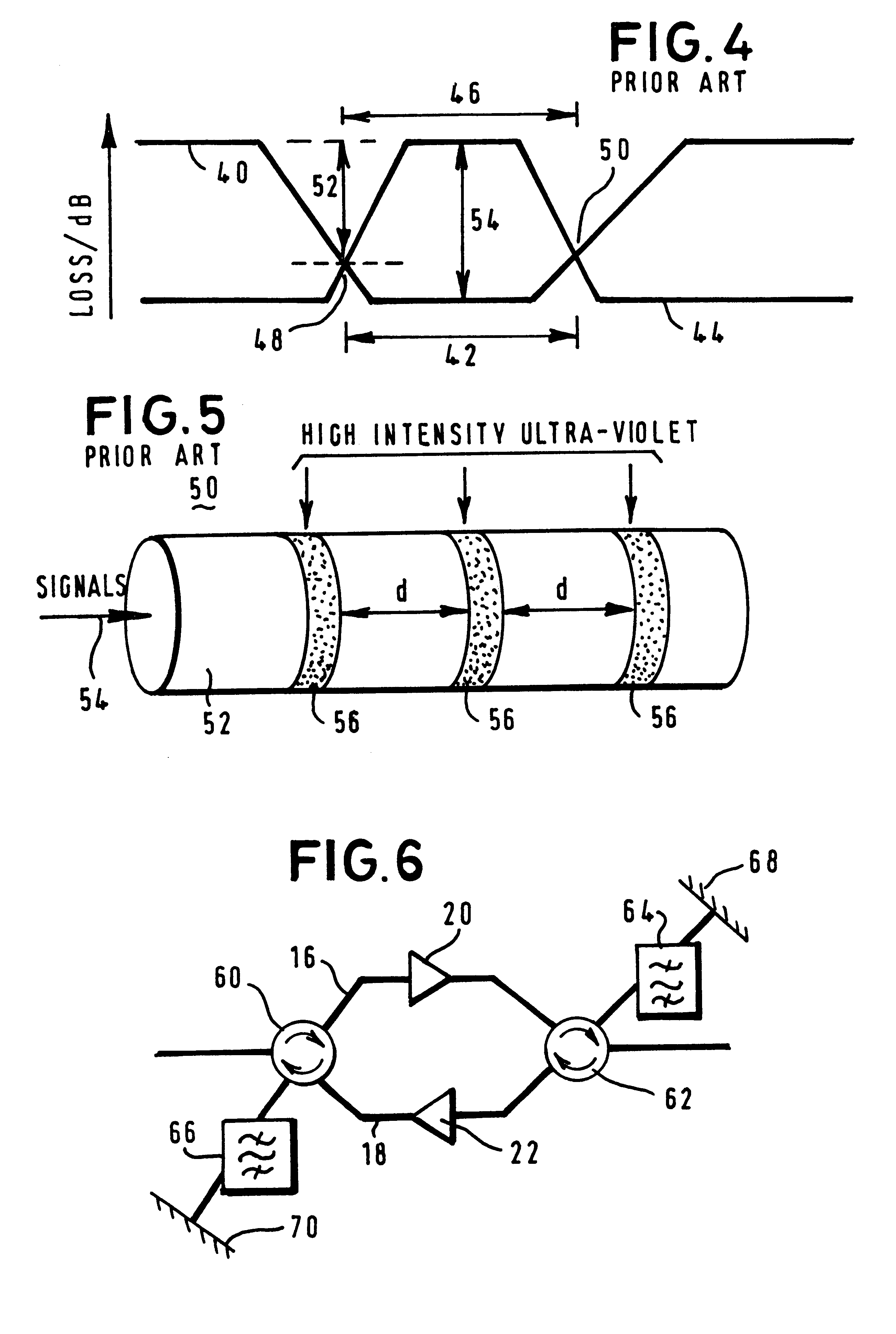
In another aspect of the present invention there is provided a circuit responsive to a
broadband optical signal supporting a plurality of channels, the circuit comprising: a directional coupler arranged to receive the broadband optical signals and configured to provide an output signal; a filter, responsive to the output signal, having a characteristic arranged to isolate from the output signal at least one desired channel on at least one filtered output; and a reflector coupled to the at least one filtered output and arranged to reflect the at least one filtered output back into the filter such that the at least one filtered output is subjected to a second filtering process that improves isolation of the at least one desired channel.


