Downhole lens assembly for use with high power lasers for earth boring

a high-power laser and lens assembly technology, which is applied in the direction of wellbore/well accessories, coal gasification, manufacturing tools, etc., can solve the problems of inability to control timed actuation of system components, and inability to drill non-linear boreholes. the arrangement of equipment is reasonably complex, and the apparatus is inherently expensiv

Inactive Publication Date: 2004-06-29
GAS TECH INST
View PDF17 Cites 98 Cited by
  • Summary
  • Abstract
  • Description
  • Claims
  • Application Information

AI Technical Summary

Benefits of technology

More particularly, it is one object of this invention to provide a downhole lens assembly for use in connection with high-powered lasers for earth boring that does not require complex apparatuses which are difficult to maintain in the field.
It is another object of this invention to provide a downhole lens assembly for use in connection with high-powered lasers for earth boring that does not require the use of movable mirrors which are difficult to position and control.
It is yet another object of this invention to provide a downhole lens assembly for use in connection with high-powered lasers for earth boring that does not require many moving parts that cannot be readily maintained in the field.
It is still a further object of this invention to provide a downhole laser assembly for use in connection with high-powered lasers for earth boring that does not require a complex assortment of minute components that are susceptible to heat damage and damage from other adverse conditions in the field.
Additionally, it is an object of this invention to provide a downhole lens assembly for use in connection with high-powered lasers for earth boring that is adaptable to use when the path of a bore is not straight, thereby rendering the apparatus suitable for directional drilling.
Still a further object of this invention is to provide a downhole lens assembly for use in connection with high-powered lasers for earth boring that transfers the laser energy downward into the hole so that it is not subject to dissipation and misdirection due to the presence of fluid, dust and / or other materials within the hole.

Problems solved by technology

This method does not utilize the laser energy to further create the hole, but rather it ignites and burns what otherwise may be valuable recoverable fossil fuels in an effort to extract, through the gas generation, liquid and gas by more conventional means.
Clearly one limitation of this system is its inability to drill non-linear boreholes.
In addition, generation of the desired annular pattern as well as controlling timed actuation of the system components requires a reasonably complex arrangement of equipment.
It will be apparent to those skilled in the art that several of these apparatuses require the use of complex and fragile equipment and some of these apparatuses are inherently expensive, difficult to operate properly, difficult to maintain and exceedingly fragile, particularly in view of the hostile environment in which they are used.
Another problem associated with conventional methods and apparatuses that utilize high power lasers for fossil fuel recovery is that they require the use of movable mirrors, which are difficult to position and to control.
Yet a further problem associated with conventional methods and apparatuses employing high power lasers for fossil fuel recovery is that they utilize many moving parts that cannot be readily maintained in the field.
Still a further problem associated with conventional methods and apparatuses employing high power lasers for fossil fuel recovery is that they require a complex assortment of relatively minute components that are susceptible to damage from numerous adverse conditions in the field, particularly in view of the surrounding hostile environment.
Yet another problem associated with conventional methods and apparatuses employing high power lasers for fossil fuel recovery is that they are not adaptable to directional drilling or holes that are other than straight.
An even further problem associated with conventional methods and apparatuses employing high power lasers for fossil fuel recovery is that a laser beam directed downward into a hole is subject to dissipation and misdirection due to the presence of fluid, dust and / or other materials within the hole.

Method used


Image

  • Downhole lens assembly for use with high power lasers for earth boring
  • Downhole lens assembly for use with high power lasers for earth boring
  • Downhole lens assembly for use with high power lasers for earth boring

Examples


Embodiment Construction

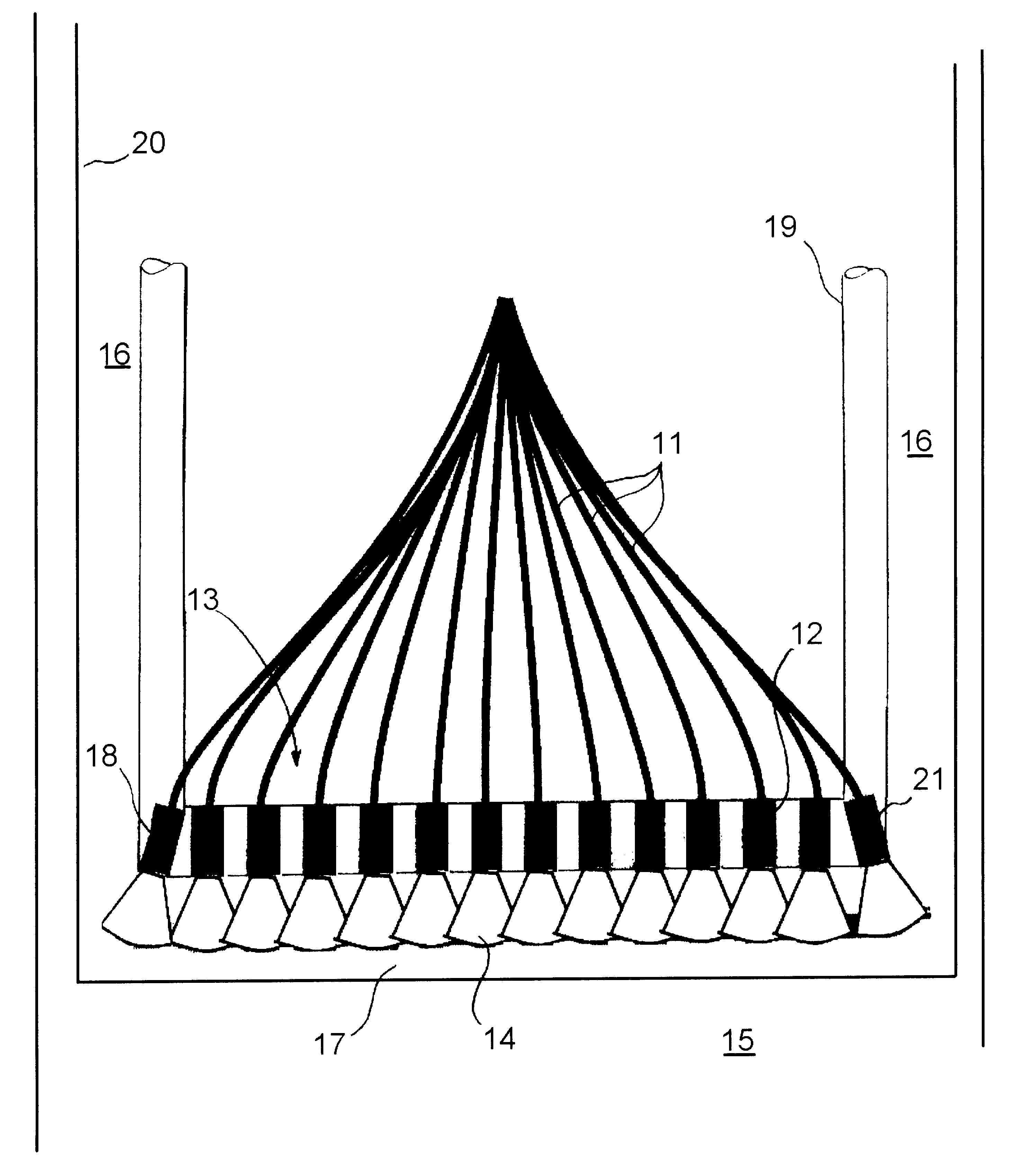
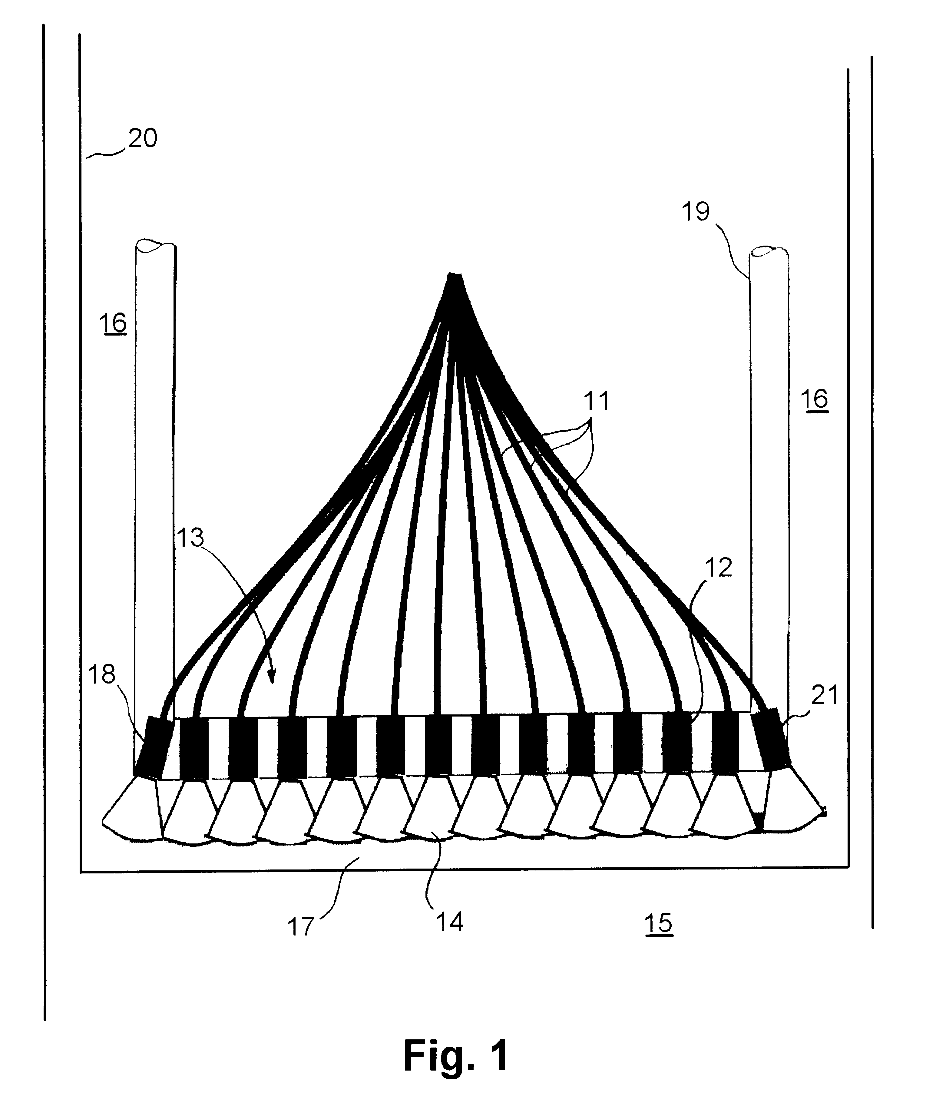
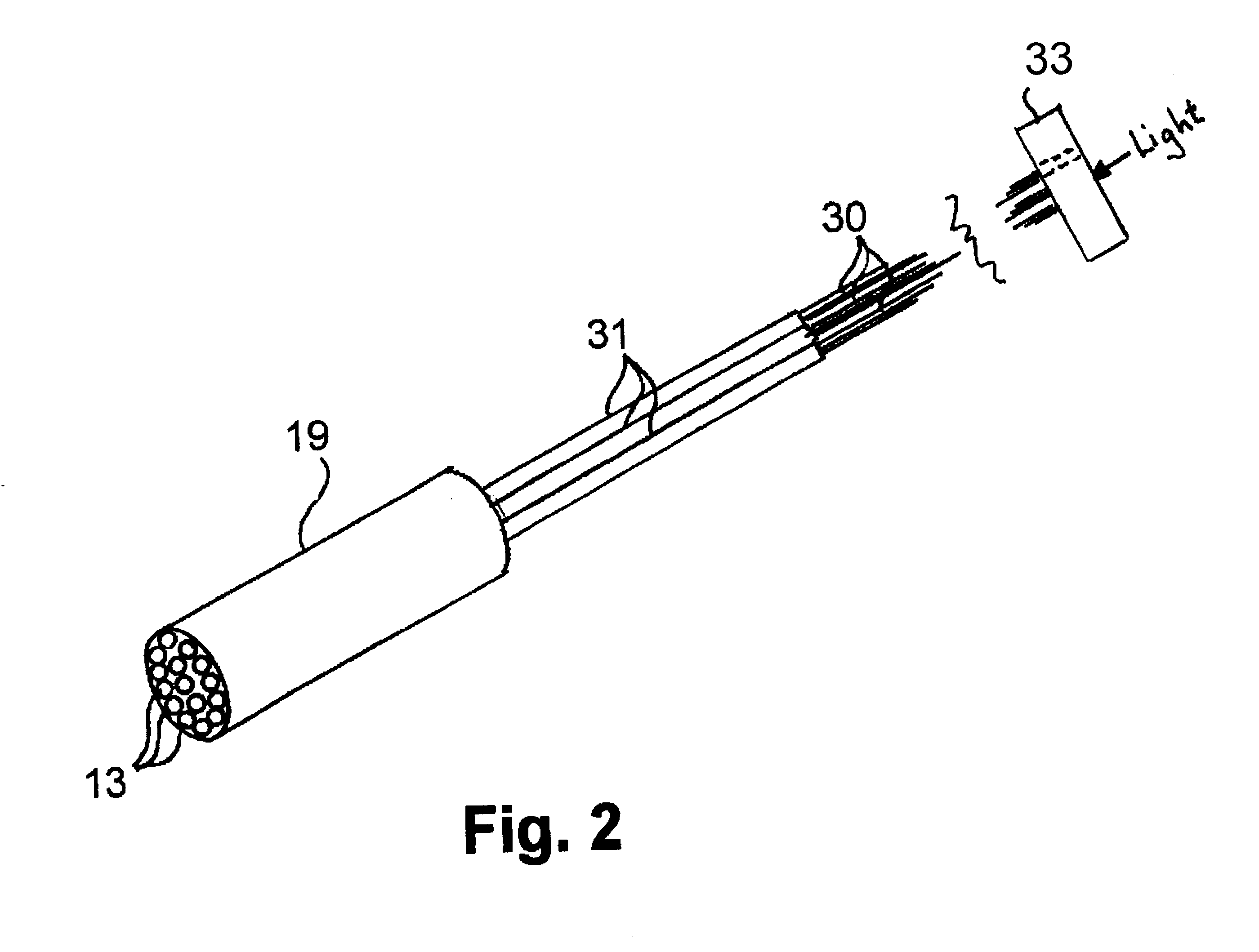
Disclosed herein is an earth boring apparatus or "drill", as shown in FIG. 1, that is at least partially locatable within a borehole 16. The apparatus comprises a plurality of optical fibers 11, each of which has a proximal fiber light energy input end, which is typically disposed above the surface of the earth and a distal fiber light energy output end, which is locatable in the borehole 16. A determining factor in the number of optical fibers 11 employed is the desired borehole size. Preferably, at least about 100 optical fibers are employed, although fewer fibers may be sufficient. Disposed at the distal fiber light energy output end of the optical fibers 11 is at least one focal lens 13. As with the number of optical fibers employed, the number of lenses 13 employed is also dependent on the desired borehole size. Focal lens 13 comprises a plurality of focal elements 12, each of which corresponds to the distal fiber light energy output end of at least one of the optical fibers 11...


PUM

PropertyMeasurementUnit
diameteraaaaaaaaaa
light energyaaaaaaaaaa
flexibleaaaaaaaaaa

Abstract

An earth boring apparatus at least partially locatable within a borehole. The apparatus includes a plurality of optical fibers, each of which has a proximal fiber light energy input end and a distal fiber light energy output end. At least one focal lens is disposed at the distal fiber light energy output end. The focal lens is made up of a plurality of focal elements, each of which corresponds to the distal fiber light energy output end of at least one optical fiber. The focal lens is arranged to receive light energy from the corresponding distal fiber light energy output end of the at least one optical fiber and focus it outwardly from the distal fiber light energy output end.

Description

1. Field of the InventionThis invention relates to a method and apparatus for earth boring in which the apparatus is locatable at least partially within a borehole. More particularly, this invention relates to a method and apparatus that utilizes high power lasers for earth boring in which an array of optical fibers is constructed and arranged to be positioned downhole in an earth boring operation in communication with a focal lens array, thereby directing laser energy at the earth to break and melt rock.2. Description of Related ArtThe use of lasers for the purpose of producing boreholes to enable the extraction of liquid and gaseous fuels from underground formations is well-known in the art. For example, U.S. Pat. No. 4,266,609 to Rom et al. teaches a method of extracting liquid and gaseous fuels from oil shale and tar sand. Using this method, kerogen and other materials can be extracted by drilling boreholes in a selected pattern through the overlying soil and rock without removi...

Claims


Application Information

Patent Timeline
Patent Type & Authority Patents(United States)
IPC IPC(8): E21B7/14E21B7/15B23K26/06B23K26/38
CPCB23K26/0604B23K26/381E21B7/14E21B7/15B23K26/4005B23K26/4075B23K26/4085B23K26/382B23K26/40B23K2103/16B23K2103/50
Inventor PARKER, RICHARD A.
Owner GAS TECH INST
Why Eureka
Try Eureka