Immersion lens with magnetic shield for charged particle beam system

a technology of charged particle beam and lens, applied in the field of immersion lenses, can solve the problems of system cost increase, and electron beam placement error, and achieve the effect of improving system cost and reducing system cos

Inactive Publication Date: 2004-07-27
APPLIED MATERIALS INC
View PDF8 Cites 6 Cited by
  • Summary
  • Abstract
  • Description
  • Claims
  • Application Information

AI Technical Summary

Benefits of technology

Various embodiments will be more fully understood in light of the following detailed description taken together with the accompanying drawings.

Problems solved by technology

The eddy currents in the above-described elements generate opposing deflection fields that deflect the electron beam, thereby creating placement error of the electron beam.
Accordingly, a disadvantage of the variable axis immersion lens is placement error caused by eddy currents generated by the deflection magnetic field.
However, the cost of the system increases with use of such materials.

Method used


Image

  • Immersion lens with magnetic shield for charged particle beam system
  • Immersion lens with magnetic shield for charged particle beam system
  • Immersion lens with magnetic shield for charged particle beam system

Examples


Embodiment Construction

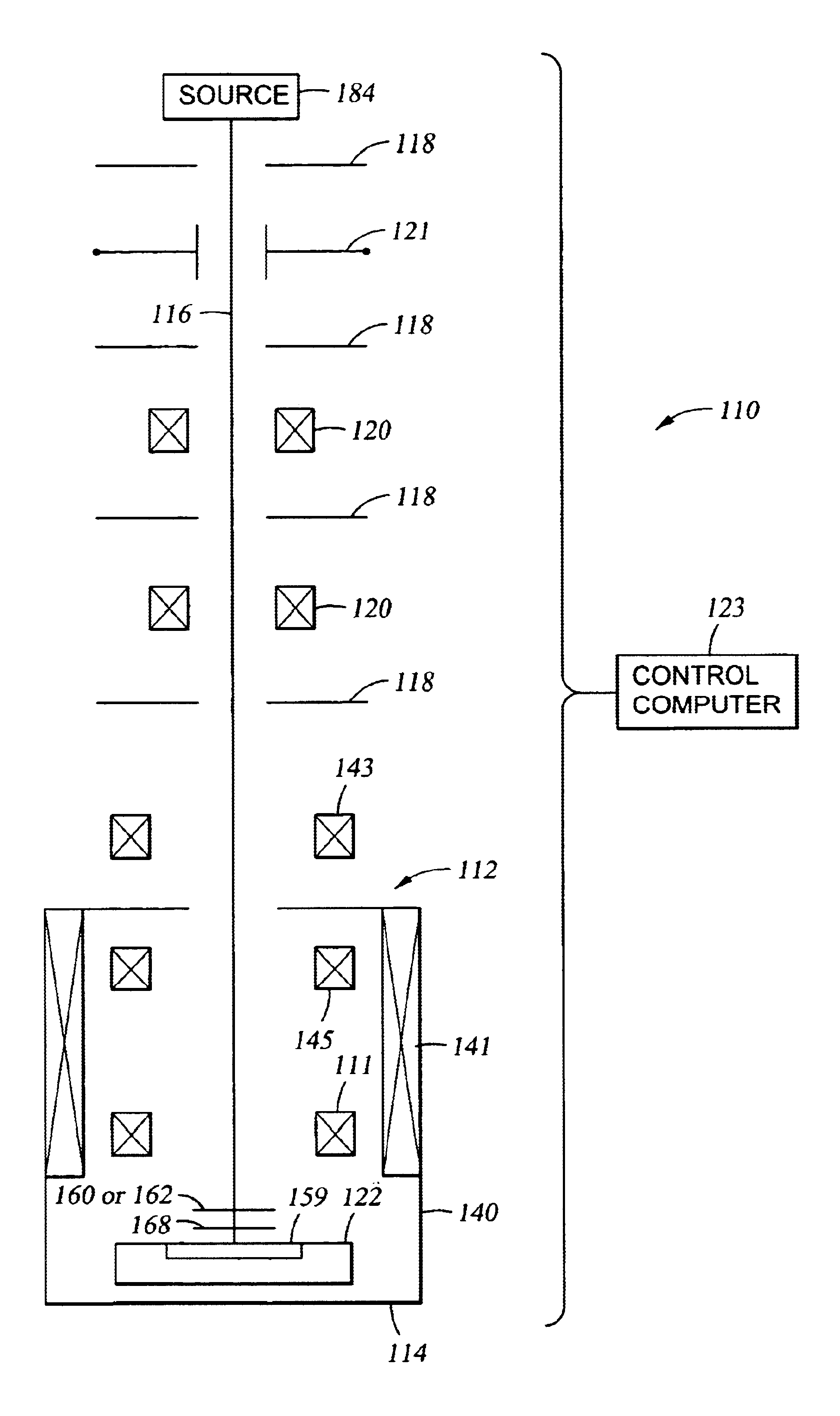
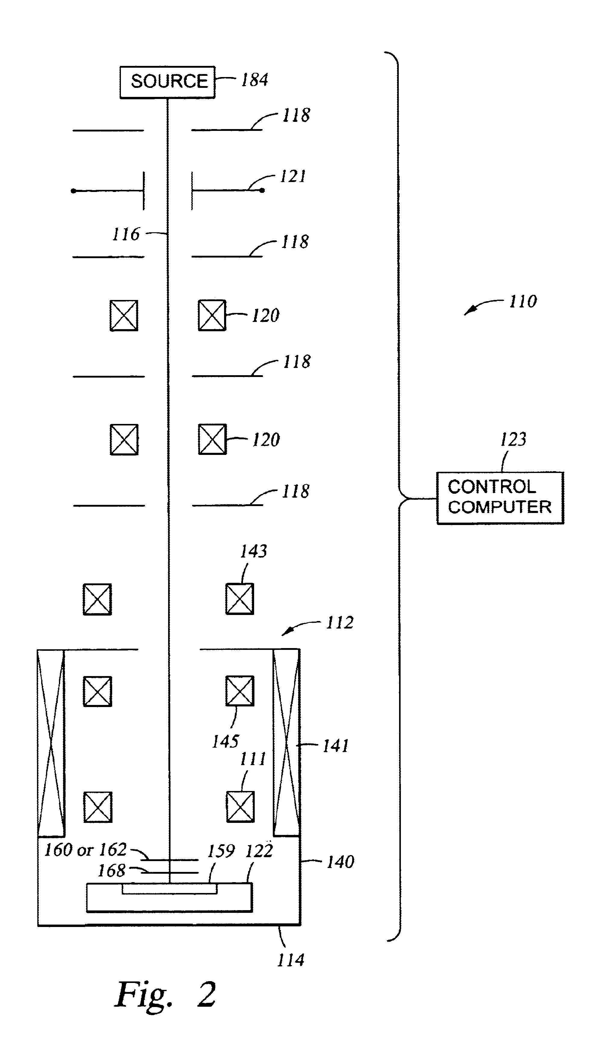
In one embodiment, an otherwise conventional charged particle beam lithography system 110 (shown in a side view in FIG. 2) includes a magnetic field shield such as a magnetically "floating" disk 160 (shown by itself in perspective view in FIG. 3B) or a magnetically "floating" cone 162 (shown by itself in perspective view in FIG. 4B). The magnetic field shield limits magnetic field 172 (FIG. 3D and FIG. 4D) generated by deflector coil 111 from radiating downstream from the magnetic field shield. The magnetic field shield does not affect magnetic field 170 (FIG. 3C and FIG. 4C) generated by excitation coil 141 because the magnetic field shield is mounted so its upper surface is parallel (or approximately parallel) to an equipotential magnetic surface 161 of magnetic field 170.

In one embodiment, lithography system 110 includes charged particle (e.g., electron) source 184, aperture plates 118, blanking deflector 121, focusing lenses 120, an immersion lens 112, stage 122, and control com...


PUM

PropertyMeasurementUnit
thicknessaaaaaaaaaa
optical axisaaaaaaaaaa
magnetic fieldaaaaaaaaaa

Abstract

An immersion lens for a charged particle beam lithography system includes a magnetically floating shield that limits a deflection magnetic field from creating eddy currents in electrically conductive components of the system downstream from the shield. The surface of the shield lies parallel or approximately parallel to a magnetic equipotential surface of the focusing magnetic field so that the shield does not affect the focusing magnetic field. The shield is, e.g., a ferrite disk or a hollow ferrite cone defining a central bore for passage of the charged particle beam.

Description

FIELD OF THE INVENTIONThe present invention relates to charged particle beam lithography and more particularly to immersion lenses for such lithography.BACKGROUNDLithography is a technique used to fabricate semiconductor devices and integrated circuits. In lithography, a target substrate (usually a mask blank or semiconductor wafer) is coated with one or more layers of photoresist materials (resist). The resist is selectively exposed to a form of radiation, such as ultraviolet light, x-rays, electrons, and ions. The resist is then developed to remove part of the resist. The remaining part of the resist protects the underlying regions of the target. Regions from which the resist has been removed are subject to various additive (e.g., lift-off) or subtractive (e.g., etching) processes that transfer a pattern onto the target surface.An electron beam or ion beam lithography system 110 (shown in FIG. 2) includes a charged particle (electron or ion) source 184 that generates a charged par...

Claims


Application Information

Patent Timeline
Patent Type & Authority Patents(United States)
IPC IPC(8): H01J37/10H01J37/141G01Q30/18H01J37/305G03F7/20H01L21/027
CPCH01J37/141H01J2237/1035H01J2237/3175
Inventor VENEKLASEN, LEE H.DEVORE, WILLIAM J.
Owner APPLIED MATERIALS INC
Why Eureka
Try Eureka