

Optical amplifier arrangement having a variably settable attenuator
- Summary
- Abstract
- Description
- Claims
- Application Information
AI Technical Summary
Benefits of technology
Problems solved by technology
Method used
Image

Examples
Embodiment Construction
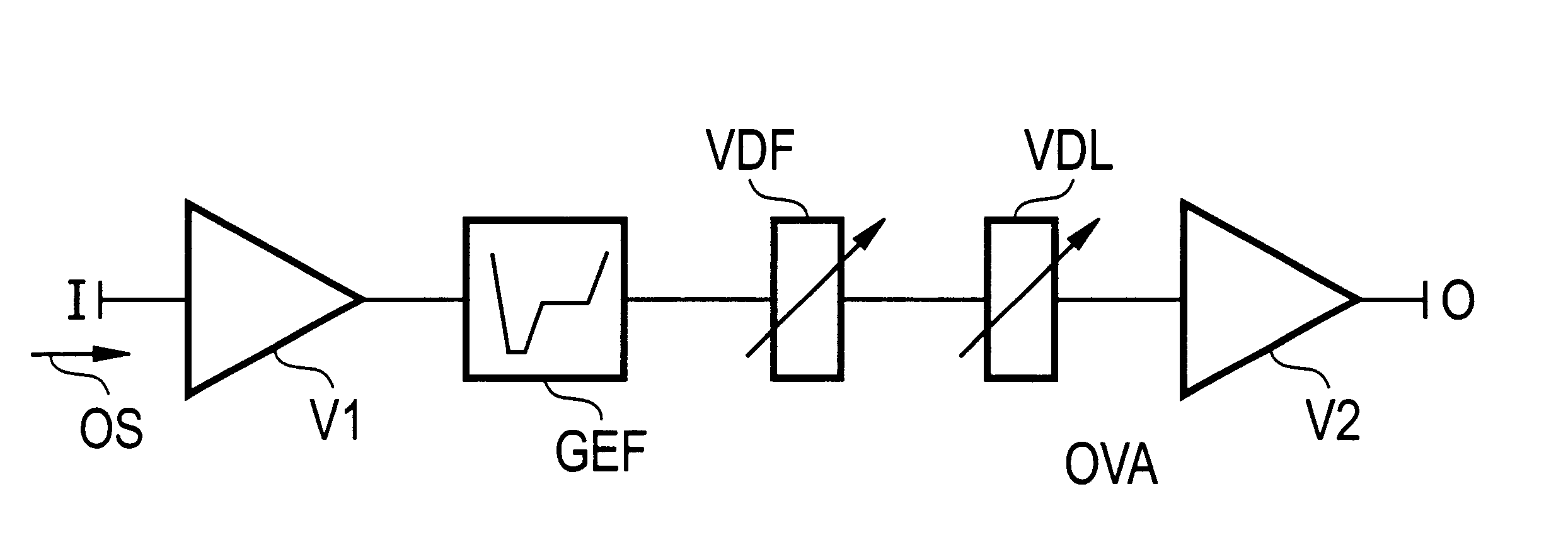
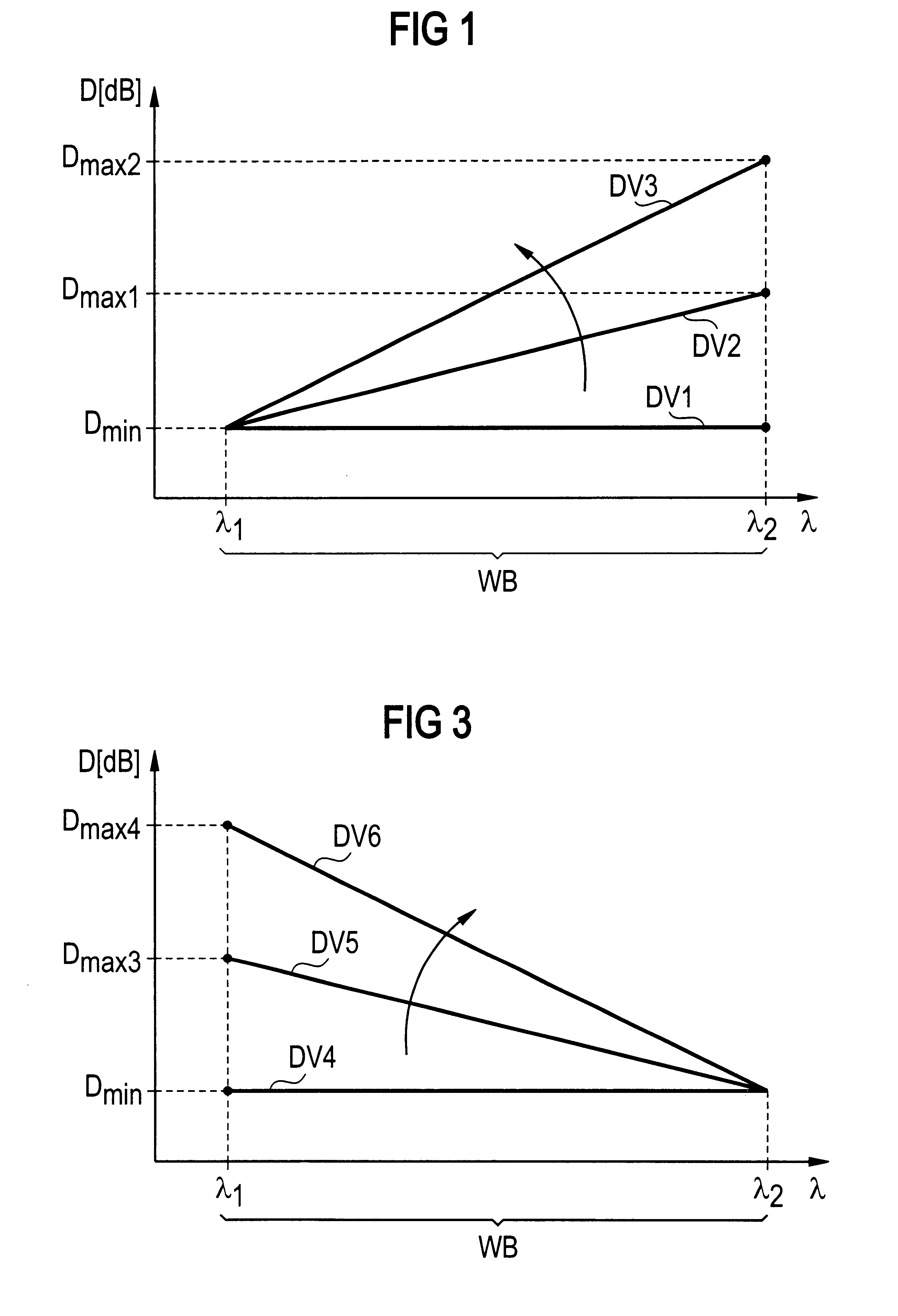
FIG. 1 represents in a diagram, by way of example, the profile of the attenuation D, or inserted attenuation, needed to compensate for tilts of the channel level spectrum, as a function of wavelength .lambda.. A first, second and third attenuation profile DV1, DV2, DV3 being represented by way of example, with a different respective dB-linear tilt for any wavelength range WB extending from a first wavelength .lambda..sub.1 to a second wavelength .lambda..sub.2. The diagram in FIG. 1 has a horizontal axis .lambda. and a vertical axis D. The wavelength .lambda. is plotted on the horizontal axis .lambda., and the different attenuation values D in dB are plotted on the vertical axis D. The dB-linear tilts, for example, of the signal level spectrum of the optical transmission signal, or optical signal OS, which are due to stimulated Raman scattering (SRS) or the temperature dependency of an erbium-doped active fiber operated, for example, in the L transmission band, are approximately rep...
PUM
 Abstract
Description
Claims
Application Information