
Humidity generating system and method and use in wood drying kiln

a technology of humidity generation system and drying kiln, which is applied in drying machines, lighting and heating apparatus, furniture, etc., can solve the problems of wood surface dries out more quickly, checking, cracking, crazing or warping, and checking the surface of wood

Inactive Publication Date: 2004-08-10
KX TECH LLC (DW US)
View PDF17 Cites 17 Cited by
  • Summary
  • Abstract
  • Description
  • Claims
  • Application Information

AI Technical Summary

Benefits of technology

It is a further object of the invention to prevent the occurrence of undesirable defects in wood such as checking, cracking, crazing or warping, by inexpensively and efficiently controlling the humidity in a wood drying kiln.
Another aspect of the invention is a method of drying wood in a kiln, comprising heating air in the kiln; adding water vapor to the air by providing water to at least one hydrophilic disk, rotating the disk or disks at speeds sufficiently high to generate a mist of fine water particles, and circulating the air to which water vapor has been added to dry the wood. This method may be thought of as lumber conditioning; that is the process used to relieve stresses that build up in lumber as a result of drying of the lumber.

Problems solved by technology

A major difficulty in drying wood is that the surface of the wood dries out more quickly than the center of a given piece.
The result is checking, cracking, crazing or warping of the wood surface.
However, the use of steam often raises the dry bulb temperature of the kiln at too high a rate.
Further many plants do not have sufficient steam capacity to provide the required amount of steam.
There is enough steam available to dry the wood, but not enough to condition it by controlling the humidity level.
This method is expensive and requires energy for the boiler to produce or atomize the moisture, while keeping the dry bulb temperature from dropping.
The approaches outlined above do not provide an apparatus or method for producing large quantities of water vapor in an inexpensive and efficient manner.
Further, these approaches do not provide any suggestion of the manner in which water vapor can be produced efficiently and inexpensively for use in a wood drying kiln.
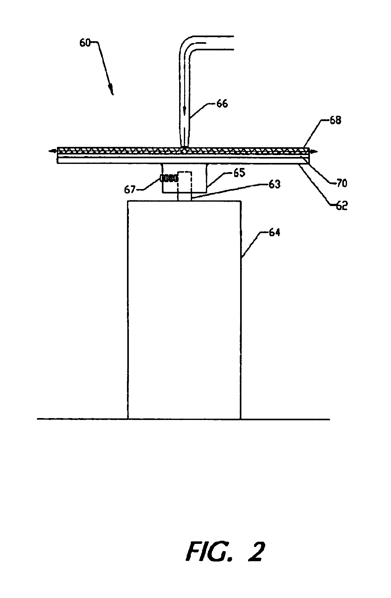
A problem that may occur is that the water may not wet the surface of disk 62, which may be formed of a stainless steel to assure adequate strength and corrosion resistance.
In this case, the water will bounce off at positions other than the rim, and will not be adequately vaporized.
This will result in less than the proper humidity being maintained, which may cause the abovementioned defects of checking, cracking or crazing to occur.
While a very thin layer of a phosphate may be deposited on disk 62 to enhance surface wetting, there is a tendency for this surface layer to wear off in a relatively short time with use.
While this approach is of value for some applications, it requires frequent maintenance.
Such interruption or lack of continuity may be undesirable in some processes, such as the wood drying process described herein, and adds to costs, in terms of lost time and the requirement for an additional inventory of parts.

Method used


Image

  • Humidity generating system and method and use in wood drying kiln
  • Humidity generating system and method and use in wood drying kiln
  • Humidity generating system and method and use in wood drying kiln

Examples


Embodiment Construction

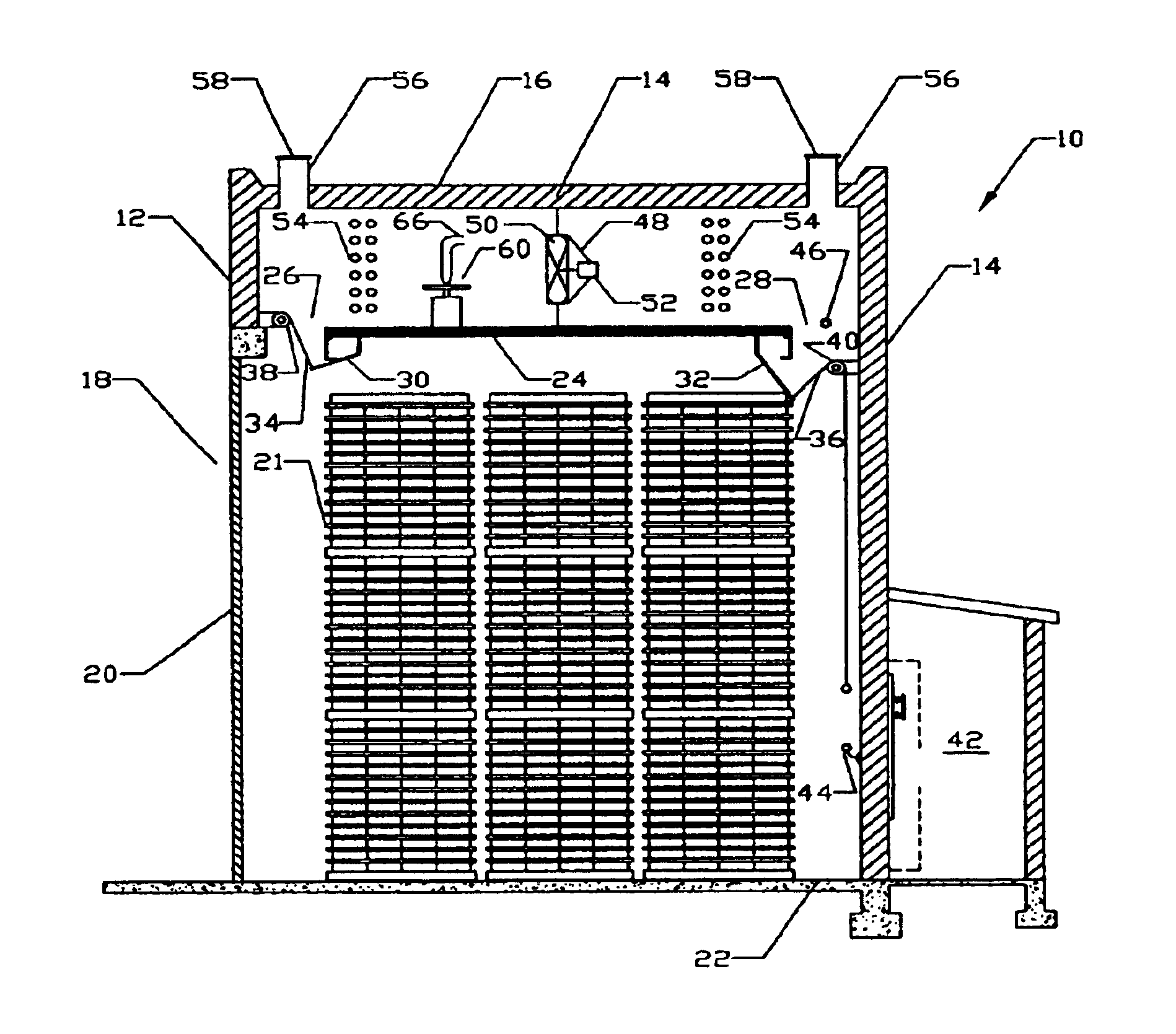
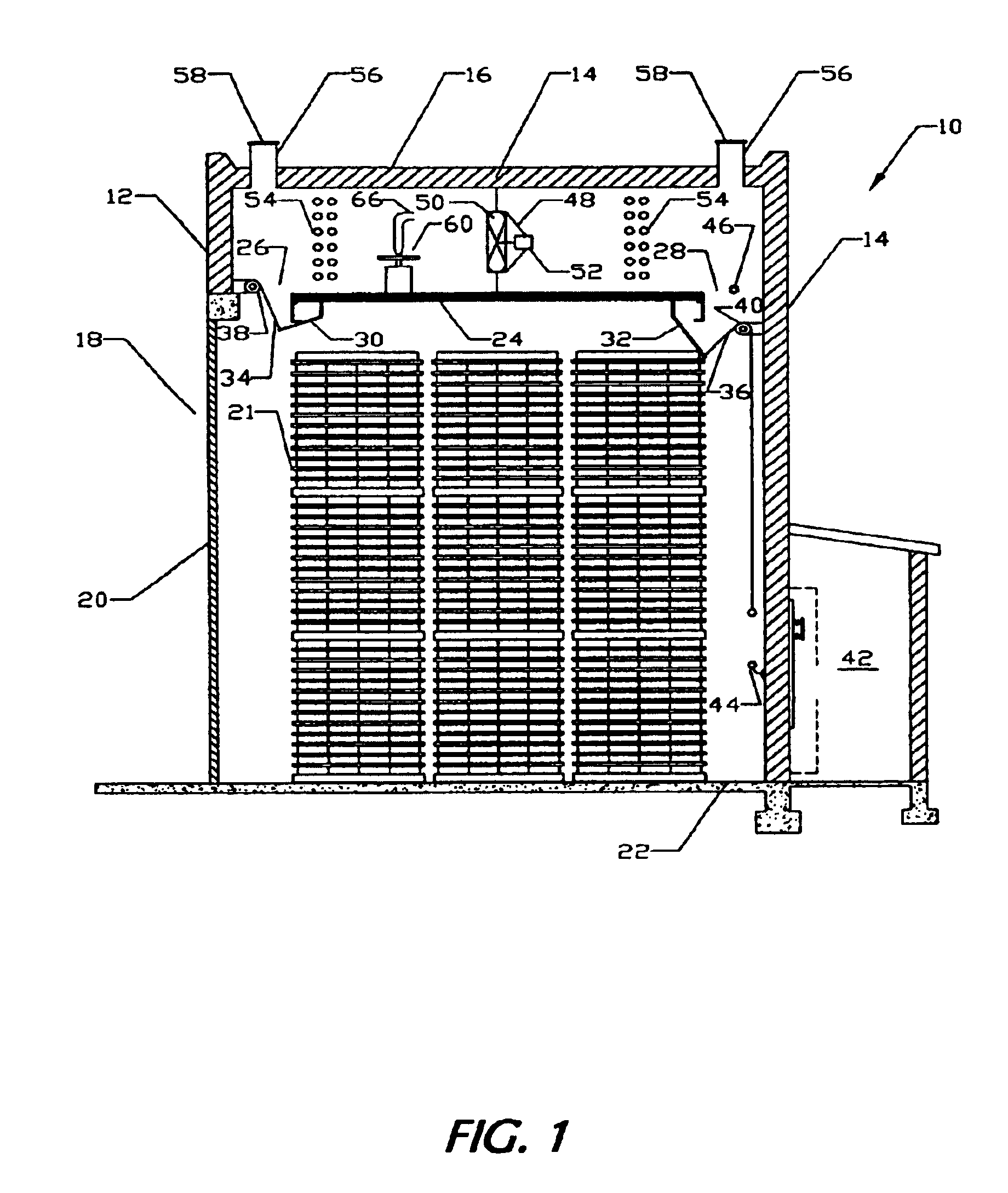
Disk 62 may have a diameter of approximately 10 inches (25.4 cm) and a thickness of approximately 0.2 inch (0.5 cm). A non-woven fabric made of a hydrophilic material or a woven cloth, such as one made from cotton may be adhered to disk 62 by a water resistant epoxy, of a type well known in the art. The disk 62 may be rotated at 3600 rpm by a totally enclosed, fan cooled, fractional horsepower motor of a type well known in the art, suitable for high temperature applications. Such motors are readily available from a number of manufacturers. At this speed of rotation, the mist formed will be distributed about a theoretical particle diameter of approximately 18 microns. This distribution will be maintained as long as the rate at which water is deposited on disk 62 does not significantly approach a maximum rate Q.sub.(max) defined in the abovementioned U.S. Pat. No. 4,604,109 to Koslow. In this example Q.sub.(max) is approximately 10 gallons (40 liters) per minute.

Such small water parti...


PUM


Abstract

An apparatus and method for generating water vapor or humidity, useful in a variety of applications, including a wood drying kiln. The apparatus may contain a hydrophilic disk, a water supply structure that supplies water so that the water is deposited on the hydrophilic disk, and a motor for rotating the disk at a speed sufficiently high so that water which is deposited on the disk is caused to leave the disk in the form of a mist of particles or droplets which are sufficiently small to evaporate rapidly to generate the water vapor. The disk may be made hydrophilic by covering with a fabric.

Description

1. Field of the InventionThe present invention relates to a system and a method used for generating water vapor so as to provide a controlled humidity environment. More particularly, it relates to an apparatus and method which may have, among other applications, the control of humidity in a wood drying kiln.2. Prior ArtLumber drying kilns put 20,000 to 100,000 board feet (or more) of various species of lumber, with various dimensions in the kiln, and then heat the closed kiln to between 1000 and 1800 Fahrenheit (approximately 380 to 820 Celsius) for many days to extract moisture from wood. Thicker pieces of harder wood take longer to dry, sometimes up to 45 days (or longer). A major difficulty in drying wood is that the surface of the wood dries out more quickly than the center of a given piece. The result is checking, cracking, crazing or warping of the wood surface. Since surface clarity is the selling feature for cost of the dried wood, the value of the wood is greatly diminished...

Claims


Application Information

Patent Timeline
Patent Type & Authority Patents(United States)
IPC IPC(8): F26B21/02F26B21/08F26B21/06
CPCF26B21/02F26B21/08F26B2210/16
Inventor KOSLOW, EVAN E.
Owner KX TECH LLC (DW US)
Learn More