
Apparatus for sensing fluid in a pipe

Inactive Publication Date: 2004-08-24
WEATHERFORD TECH HLDG LLC
View PDF99 Cites 204 Cited by
  • Summary
  • Abstract
  • Description
  • Claims
  • Application Information

AI Technical Summary

Benefits of technology

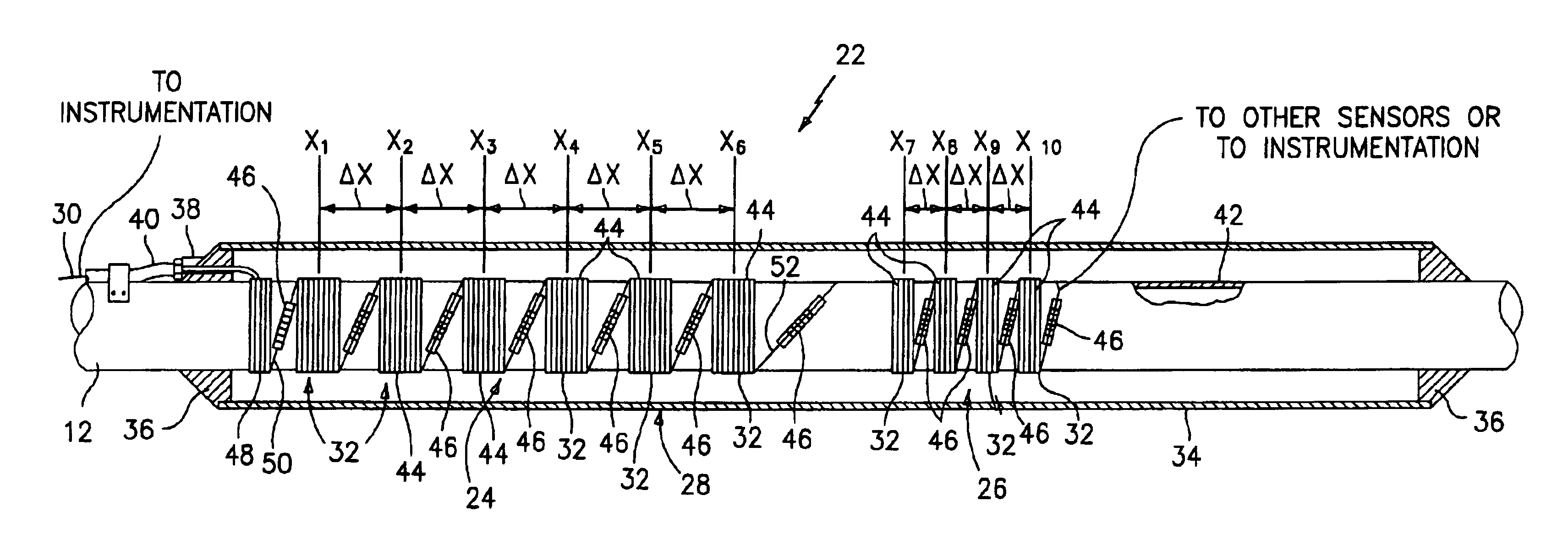
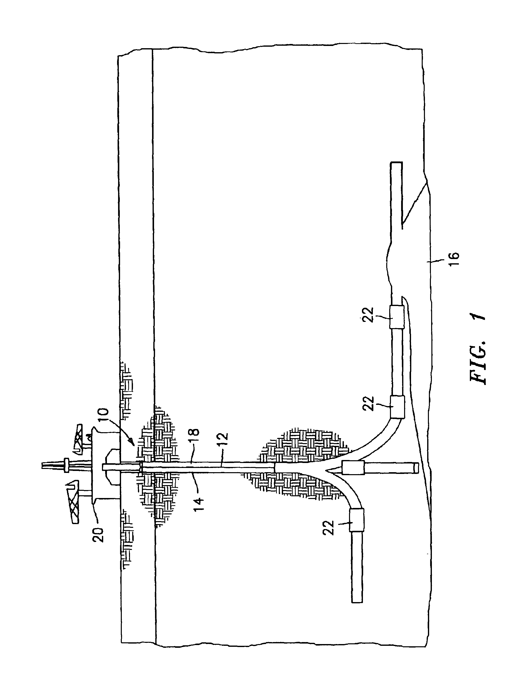
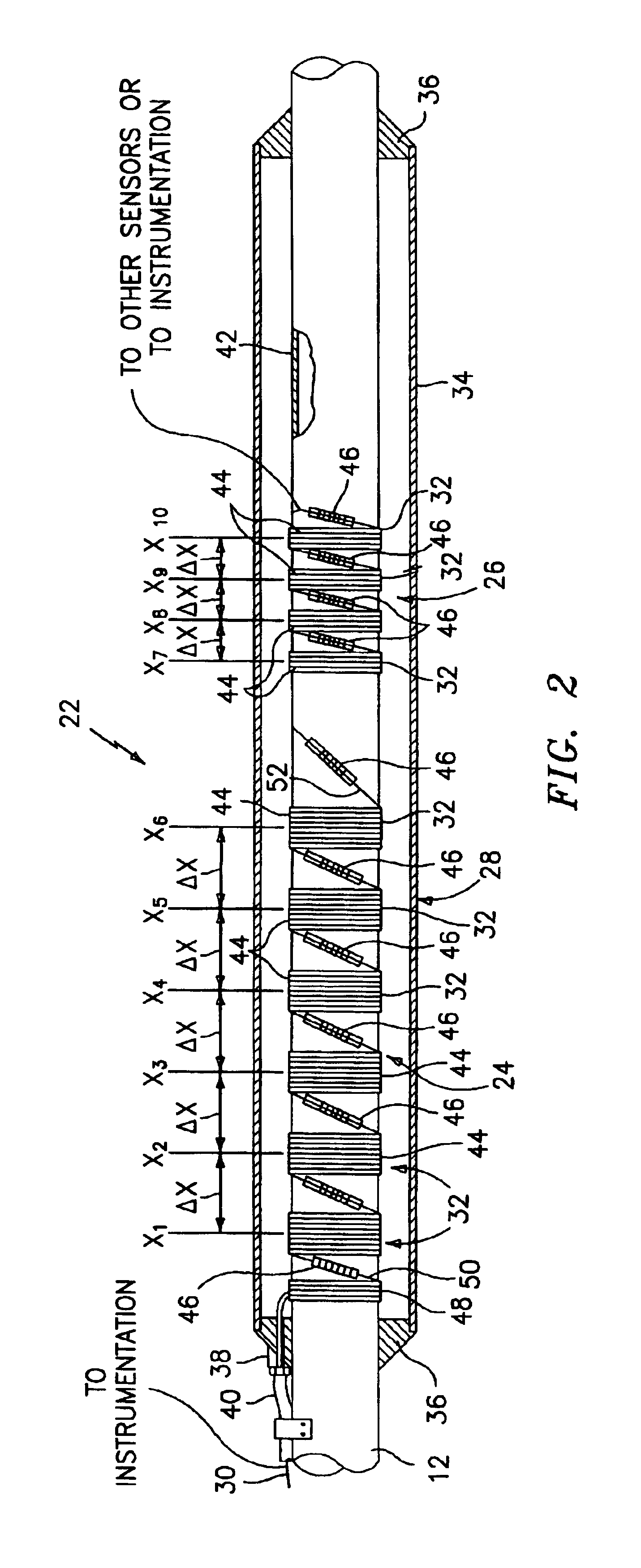
An advantage of the present invention apparatus is it enables the collection of flow data downhole within a well at or near the source of the fluid flow. As a result, accurate flow data can be collected from one or more sources individually, rather than data compiled from a mixture of those sources. Fluid flow data from the different sources enables the determination of the velocity and phase fraction of fluids flowing from each source.
Another advantage of the present invention is that it provides fluid flow data in a nonintrusive manner. The sensing arrays of the present invention attach to the outer surface of the pipe and therefore do not require an opening extending into the fluid flow path. As a result, a potential leak path into or out of the fluid flow path is eliminated and the sensing arrays are protected from the fluid flow within the pipe.
The present apparatus is also protected from the environment outside of the production pipe by a compactly formed housing that can easily be placed within the well casing. The housing protects the sensing arrays from the fluid and debris that enters the annulus between the production pipe and the well casing. As a result, the present invention can use a wider variety of sensing devices than would otherwise be possible. In addition, in the embodiment where the sensing arrays are disposed within a pressure vessel, the sensing arrays are disposed within a gas environment at a substantially constant pressure. The gaseous environment within the housing substantially isolates the sensing arrays from the acoustic environment outside of the housing. Hence, fluctuations in the pressure outside of the pressure vessel that might influence the sensing arrays are effectively attenuated. For all of these reasons, the reliability and durability of the sensing arrays are accordingly improved, and the need for a replacement or recalibration is reduced.
Other advantages of the present invention flow from the fact that it utilizes pressure sensing that is circumferentially averaged. Circumferential averaging helps to filter out non-axisymmetric pressure disturbances such as those associated with transverse pipe vibrations, flow noise, and higher dimensional acoustic oscillations as well as non-uniformities of the fluid flow through the cross-sectional area of the pipe. This attribute is useful for measuring propagating one-dimensional acoustic waves as well as long lengthscale vortical disturbances.

Problems solved by technology

These devices have several drawbacks including the fact that they provide an undesirable flow impediment, arc subject to the hostile environment within the pipe, and typically provide undesirable potential leak paths into or out of the pipe.
In addition, these devices are only able to provide information relating to the bulk fluid flow and are therefore unable to provide information specific to constituents within a multi-phase fluid flow.
A disadvantage of this type of technique is that gas bubbles and / or particulates in the fluid can interfere with the signals traveling back and forth between the transceivers.
Another disadvantage of this type of technique is that it considers only the fluid disposed between transceivers during the signal transit time.
A problem with utilizing a flow meter at the wellhead of a multiple source well is that the fluid reaching the flow meter is a mixture of the fluids from the various sources, which are disposed at different positions within the well.
So although the multiphase flow meter provides the advantage of providing information specific to individual constituents within a fluid (which is an improvement over bulk flow sensors), the information they provide is still limited because there is no way to distinguish from the various sources.
Acquiring reliable, accurate fluid flow data downhole at a particular source environment is a technical challenge for at least the following reasons.
First, fluid flow within a production pipe is hostile to sensors in direct contact with the fluid flow.
Fluids within the production pipe can erode, corrode, wear, and otherwise compromise sensors disposed in direct contact with the fluid flow.
In addition, the hole or port through which the sensor makes direct contact, or through which a cable is run, is a potential leak site.
Second, the environment within most wells is harsh, characterized by extreme temperatures, pressures, and debris.
Extreme temperatures can disable and limit the life of electronic components.
Third, the well environment makes it difficult and expensive to access most sensors once they have been installed and positioned downhole.

Method used


Image

  • Apparatus for sensing fluid in a pipe
  • Apparatus for sensing fluid in a pipe
  • Apparatus for sensing fluid in a pipe

Examples


Embodiment Construction

also describes the present apparatus as being used within a well enviromnent with the sensing arrays 24, 26 deployed together. Although the present apparatus has particular utility in a well enviromnent, it can be used to measure fluid flow in a pipe 12 in a variety of applications and is therefore not limited to a well application. Likewise, there is no requirement that the acoustic sensing array 24 and the flow velocity sensing arrays 26 must be utilized together, and each can be used individually to suit the application.


PUM


Abstract

An apparatus for non-intrusively sensing fluid flow within a pipe is provided. The apparatus includes a first sensing array for sensing acoustic signals traveling at the speed of sound through fluid flow within the pipe, a second sensing array for sensing local pressure variations traveling with the fluid flow, and a housing attached to the pipe for enclosing the sensing arrays. The first sensing array includes a plurality of first optical pressure sensors and the second sensing array includes a plurality of second optical pressure sensors.

Description

1. Technical FieldThis invention relates to fluid flow sensing devices that use fiber optics, and, more particularly, to those devices that measure the speed of sound, flow velocity, and other parameters of a fluid within a pipe using acoustic signals and local short duration pressure variations within the fluid.2. Background InformationIn the petroleum industry, there is considerable value in the ability to monitor the flow of petroleum products in the production pipe of a well in real time. Historically, fluid flow parameters such as the bulk velocity of a fluid have been sensed with venturi type devices directly disposed within the fluid flow. These devices have several drawbacks including the fact that they provide an undesirable flow impediment, arc subject to the hostile environment within the pipe, and typically provide undesirable potential leak paths into or out of the pipe. In addition, these devices are only able to provide information relating to the bulk fluid flow and ...

Claims


Application Information

Patent Timeline
IPC IPC(8): G01F1/66
CPCE21B47/102G01F1/666G01F1/668E21B47/113E21B47/114
Inventor DAVIS, ALLEN R.GYSLING, DANIEL L.WINSTON, CHARLES R.FAUSTINO, JOHN M.MCGUINN, REBECCA S.
Owner WEATHERFORD TECH HLDG LLC
Learn More