Methods and apparatus for forming curved axial bores through spinal vertebrae

a technology of spinal vertebrae and axial bores, which is applied in the direction of prosthesis, surgical forceps, therapy, etc., can solve the problems of neurologic deficit in nerve function, clinical outcomes are not consistently satisfactory, and pain experiences are usually extreme and debilitating

Inactive Publication Date: 2004-09-14
MIS IP HLDG LLC
View PDF169 Cites 524 Cited by
  • Summary
  • Abstract
  • Description
  • Claims
  • Application Information

AI Technical Summary

Problems solved by technology

Patients who suffer from such conditions usually experience extreme and debilitating pain and often neurologic deficit in nerve function.
Although damaged discs and vertebral bodies can be identified with sophisticated diagnostic imaging, the surgical procedures are so extensive that clinical outcomes are not consistently satisfactory.
Furthermore, patients undergoing presently available fusion surgery experience significant complications and uncomfortable, prolonged convalescence.
Such techniques have been used effectively to treat the above described conditions and to relieve pain suffered by the patient However, there are still disadvantages to the present fixation implants and surgical implantation techniques.
Since the pedicles of vertebrae above the second lumbar vertebra (L2) are very small, only small bone screws can be used which sometimes do not give the needed support to stabilize the spine.
These rods and screws and clamps or wires are surgically fixed to the spine from a posterior approach, and the procedure is difficult.
These approaches are criticized as failing to provide adequate medial-lateral and rotational support in the '899 patent.
The large hole or holes can compromise the integrity of the vertebral bodies, and if drilled too posteriorly, can injure the spinal cord.
The telescoping causes the length of the vertebral column to shorten and can cause damage to the spinal cord and nerves that pass between the two adjacent vertebrae.
The posterolateral or anterior lateral approach is necessitated to correct the severe spondylolisthesis displacement using the reduction tool and results in tissue injury.
As a result, the spinal column can be further weakened and / or result in surgery induced pain syndromes.
Only a limited access to and alignment of S1 and L5 can be achieved by this approach because the distal ends of the straight bore and shaft approach and threaten to perforate the anterior surface of the L5 vertebral body.
The sheath or guide is advanced through the bore as the bore is made, making it not possible for the user to adjust the curvature of the bore to track physiologic features of the bone that it traverses.

Method used


Image

  • Methods and apparatus for forming curved axial bores through spinal vertebrae
  • Methods and apparatus for forming curved axial bores through spinal vertebrae
  • Methods and apparatus for forming curved axial bores through spinal vertebrae

Examples


Embodiment Construction

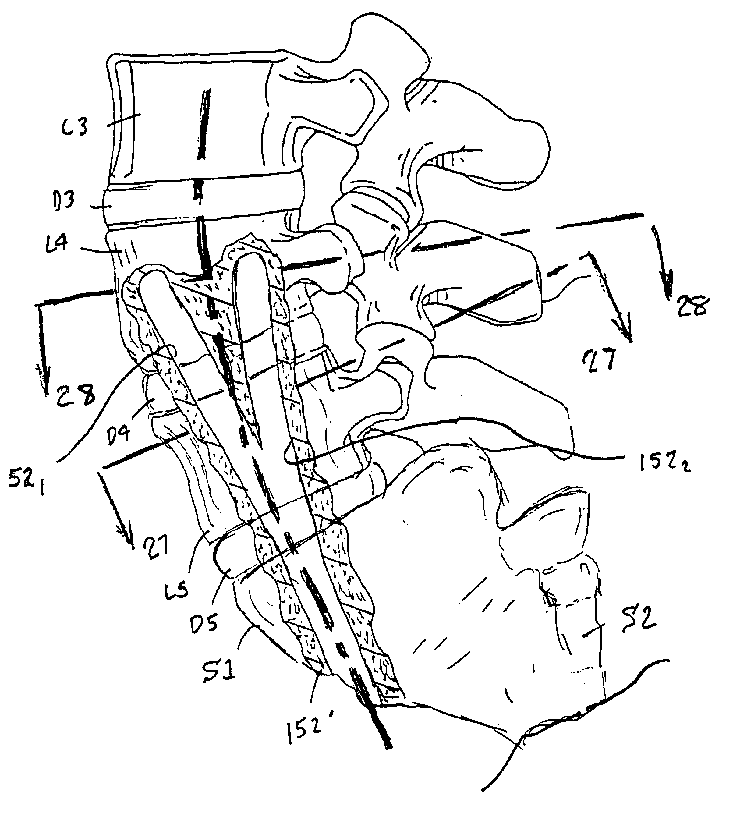
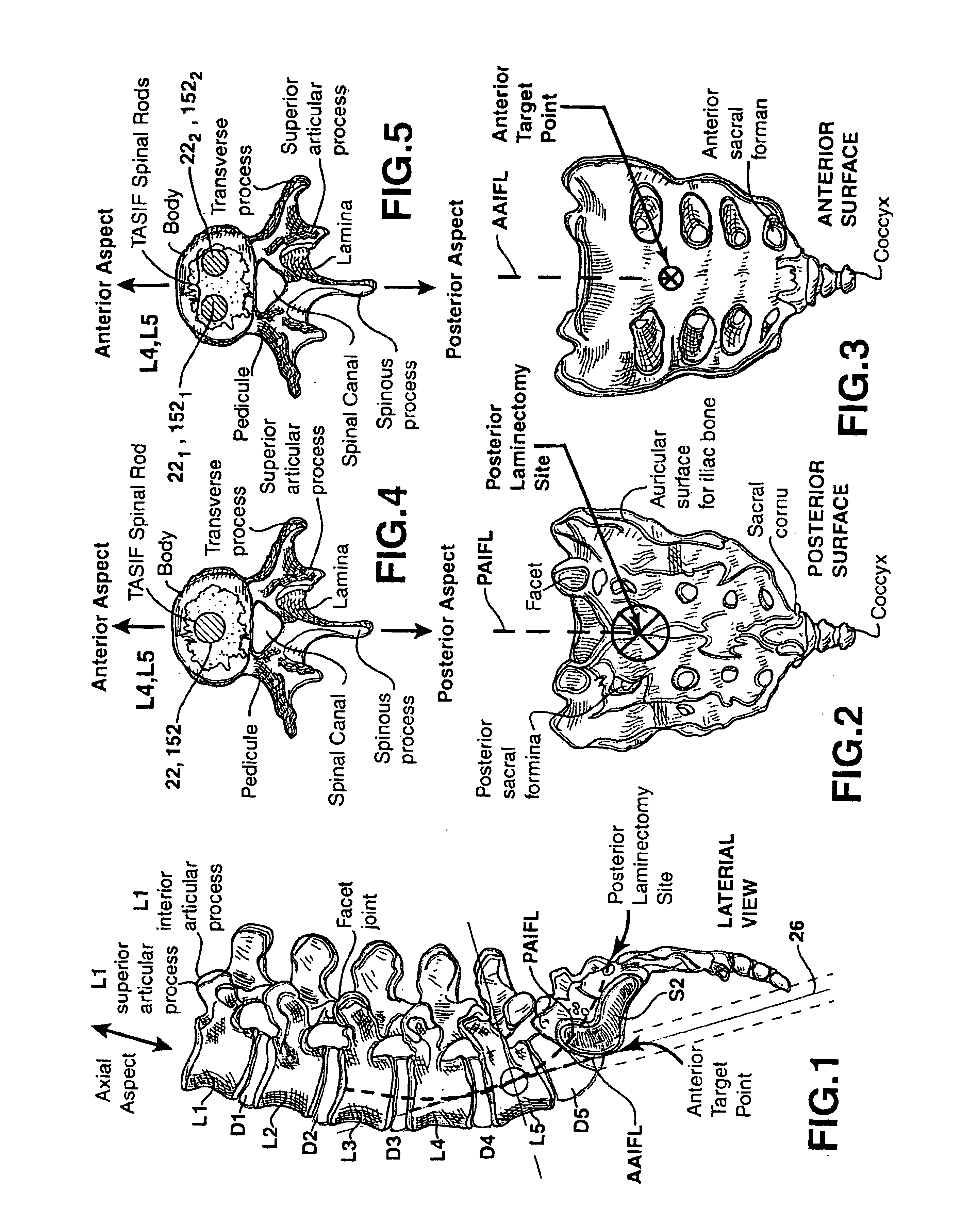
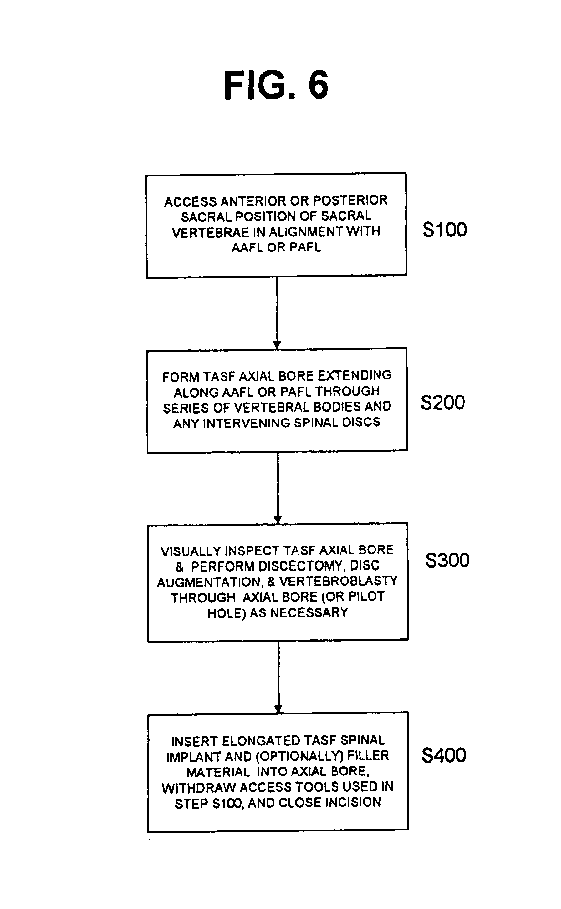
The methods and surgical instrumentation and spinal implants disclosed in the above-referenced provisional application No. 60 / 182,748 and in co-pending, commonly assigned, patent application Ser. No. 09 / 640,222 filed Aug. 16,2000, for METHOD AND APPARATUS FOR PROVIDING POSTERIOR OR ANTERIOR TRANS-SACRAL ACCESS TO SPINAL VERTEBRAE can be employed in the practice of the present invention. The '222 application discloses a number of related TASIF methods and surgical tool sets for providing posterior and anterior trans-sacral access to a series of adjacent vertebrae located Within a human lumbar and sacral spine having an anterior aspect, a posterior aspect and an axial aspect, the vertebrae separated by intact or damaged spinal discs. Certain of the tools are selectively employed to form a percutaneous (i.e., through the skin) pathway from an anterior or posterior skin incision to a respective anterior or posterior position, e.g., a target point of a sacral surface or the cephalad end ...


PUM

PropertyMeasurementUnit
diameteraaaaaaaaaa
diameteraaaaaaaaaa
diametersaaaaaaaaaa

Abstract

One or more curved axial bore is formed commencing from an anterior or posterior sacral target point and cephalad through vertebral bodies in general alignment with a visualized, trans-sacral axial instrumentation / fusion (TASIF) line in a minimally invasive, low trauma, manner. An anterior axial instrumentation / fusion line (AAIFL) or a posterior axial instrumentation / fusion line (PAIFL) that extends from the anterior or posterior target point, respectively, in the cephalad direction following the spinal curvature through one or more vertebral body is visualized by radiographic or fluoroscopic equipment. Generally curved anterior or posterior TASIF axial bores are formed in axial or parallel or diverging alignment with the visualized AAIFL or PAIFL, respectively. The anterior and posterior TASIF axial bore forming tools can be manipulated from proximal portions thereof to adjust the curvature of the anterior or posterior TASIF axial bores as they are formed in the cephalad direction. The boring angle of the distally disposed boring member or drill bit can be adjusted such that selected sections of the generally curved anterior or posterior TASIF axial bores can be made straight or relatively straight, and other sections thereof can be made curved to optimally traverse vertebral bodies and intervening disc, if present.

Description

The present invention relates generally to spinal surgery, particularly methods and apparatus for forming one or more curved axial bore through vertebral bodies in general alignment with a visualized, trans-sacral axial instrumentation / fusion (TASIF) line in a minimally invasive, low trauma, manner.It has been estimated that 70% of adults have had a significant episode of back pain or chronic back pain emanating from a region of the spinal column or backbone. Many people suffering chronic back pain or an injury requiring immediate intervention resort to surgical intervention to alleviate their pain.The spinal column or back bone encloses the spinal cord and consists of 33 vertebrae superimposed upon one another in a series which provides a flexible supporting column for the trunk and head. The vertebrae cephalad (i.e., toward the head or superior) to the sacral vertebrae are separated by fibrocartilaginous intervertebral discs and are united by articular capsules and by ligaments. T...

Claims


Application Information

Patent Timeline
Patent Type & Authority Patents(United States)
IPC IPC(8): A61B17/17A61B17/32A61B17/16A61B17/88A61B17/70A61F2/44A61F2/46A61B17/22A61B17/28A61B17/60A61B17/66A61F2/30A61F2/00A61F2/28A61B17/00A61N5/10A61B17/56A61B
CPCA61B17/1617A61B17/1671A61B17/1757A61B17/32002A61B17/320758A61B17/70A61F2/441A61F2/4465A61F2/4601A61F2/4611A61B17/320725A61B17/66A61B17/7055A61B17/8805A61B2017/00261A61B2017/00734A61B2017/00867A61B2017/2905A61B2017/320733A61F2/442A61F2/4455A61F2002/2821A61F2002/2835A61F2002/30092A61F2002/30291A61F2002/3055A61F2002/30563A61F2002/30566A61F2002/30677A61F2002/30774A61F2002/30841A61F2002/3085A61F2002/30879A61F2002/30884A61F2002/30892A61F2002/30925A61F2002/3097A61F2002/4475A61F2002/448A61F2210/0014A61F2230/0091A61F2310/00353A61N5/1027Y10S606/914A61F2002/30593
Inventor CRAGG, ANDREW H.KAGAN, JONATHAN
Owner MIS IP HLDG LLC
Why Eureka
Try Eureka