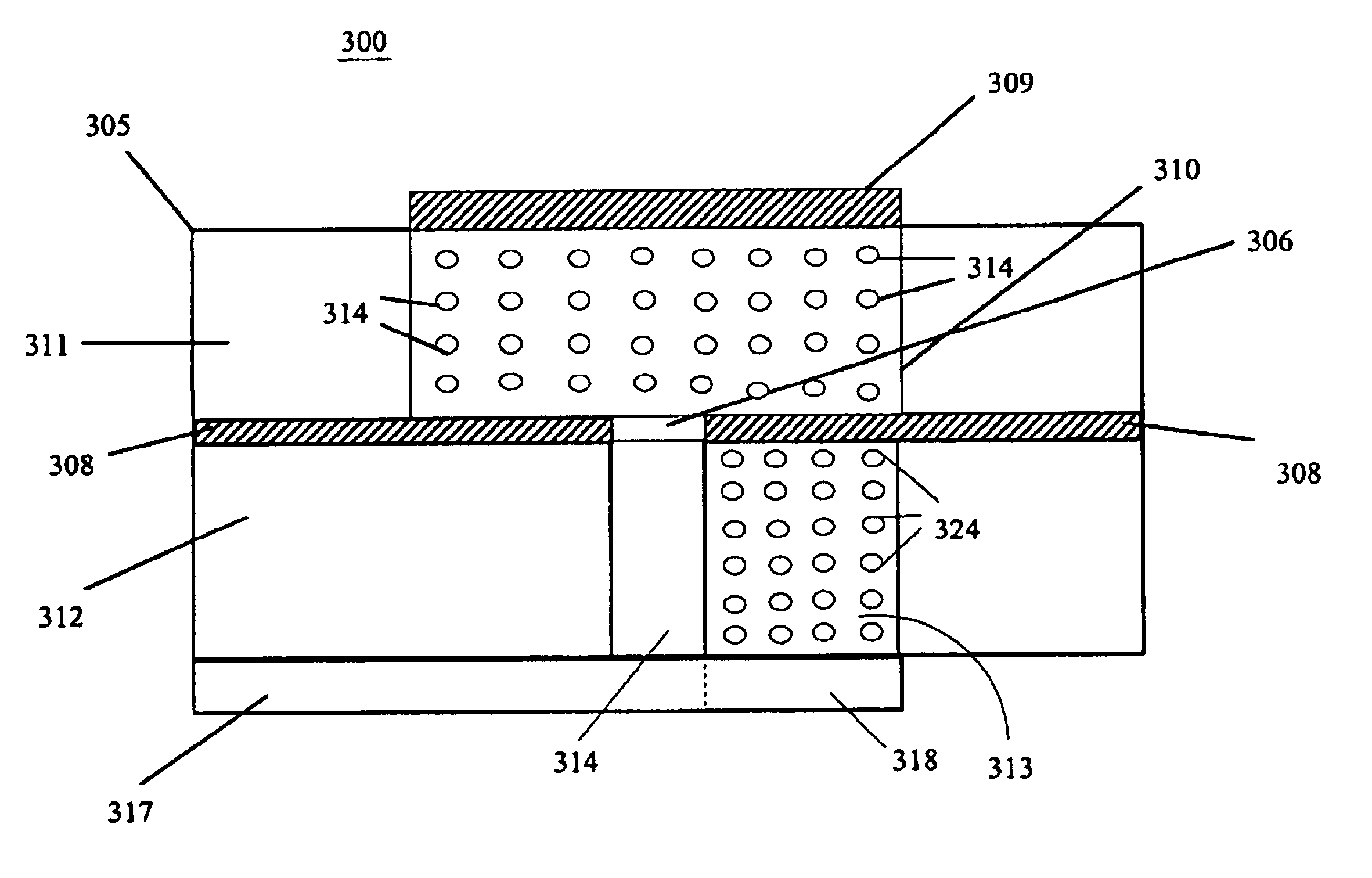
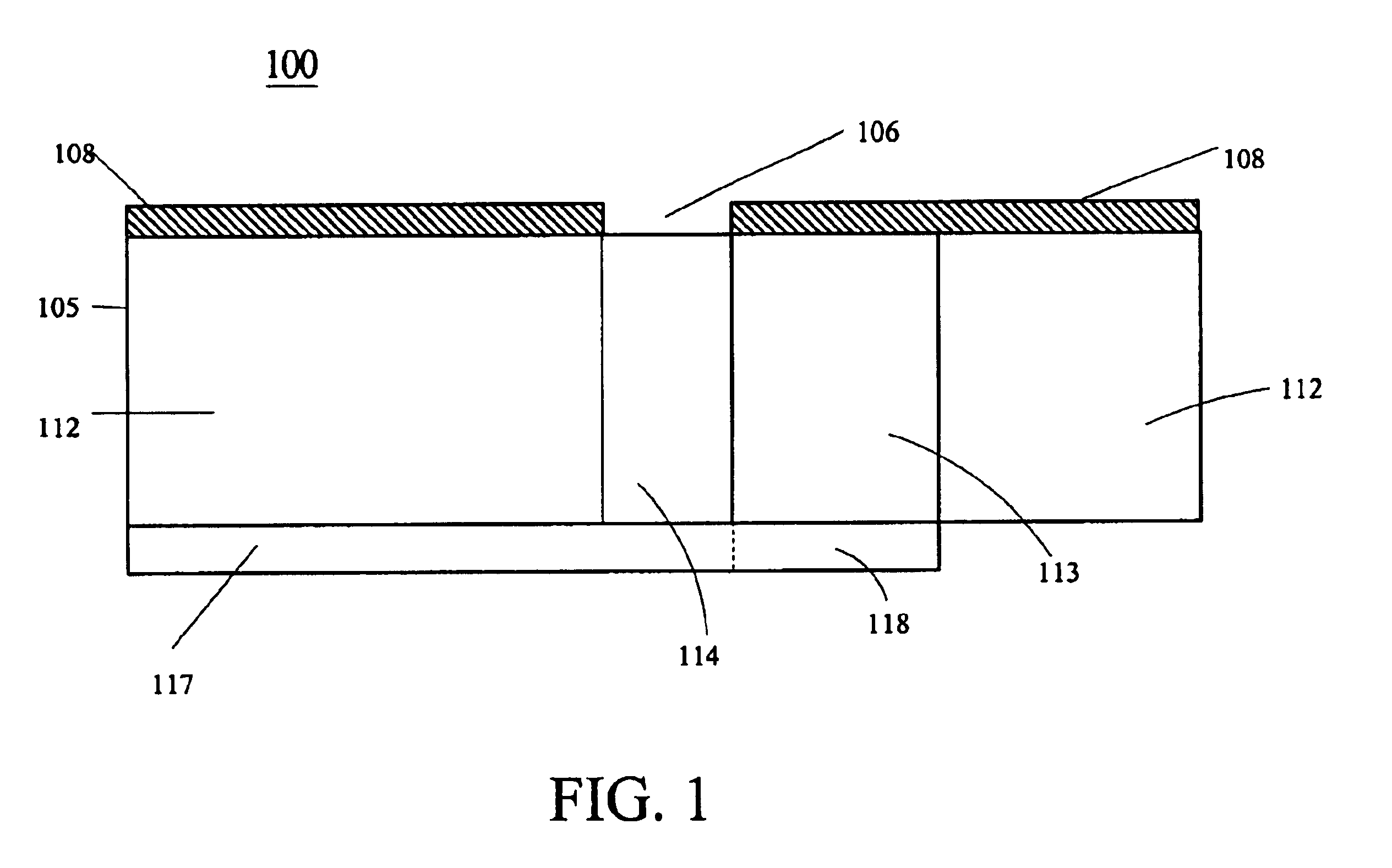
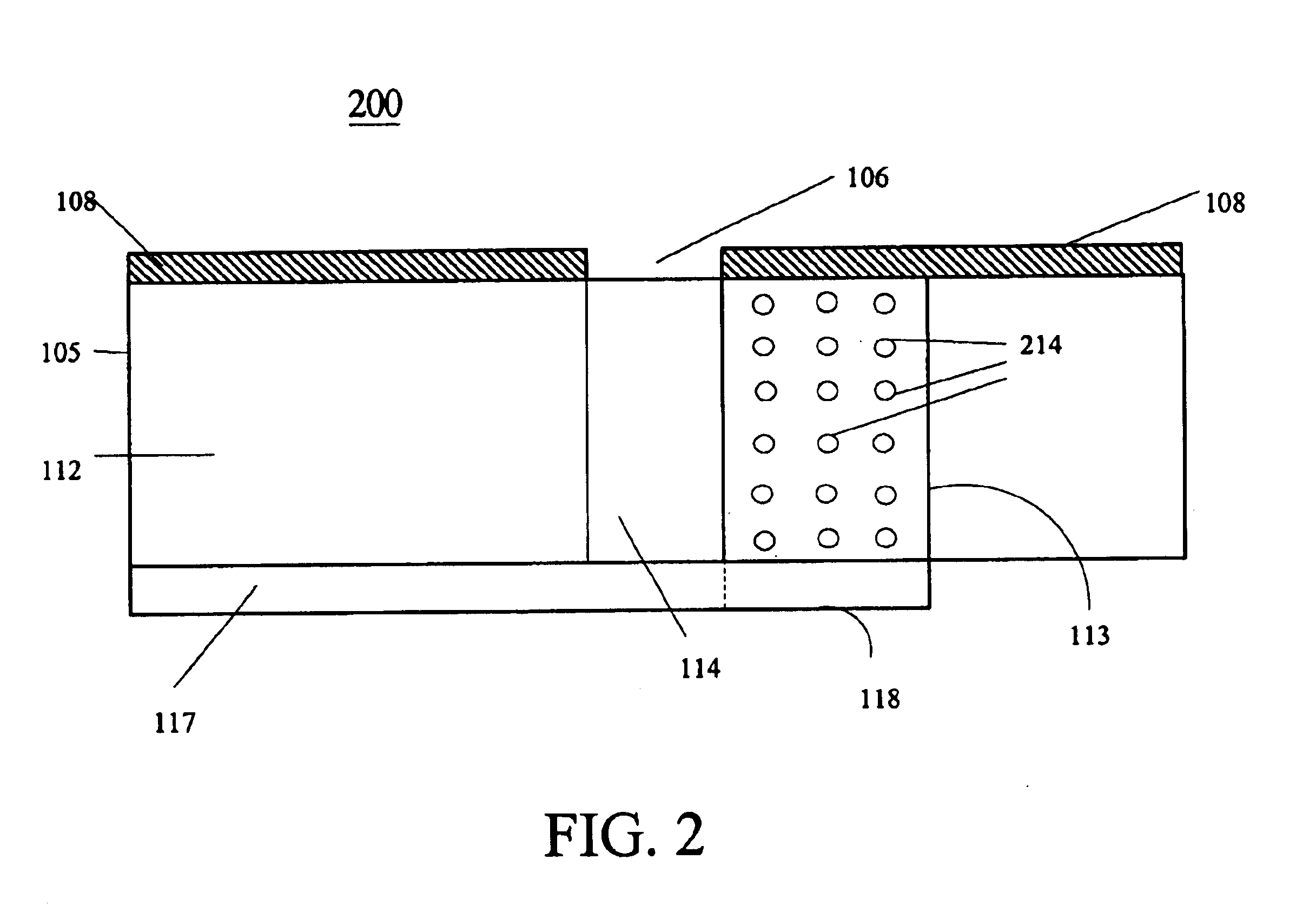
High efficiency slot fed microstrip antenna having an improved stub
a microstrip antenna and high efficiency technology, applied in the field of slot antennas, can solve the problems of inconvenient design of circuit components, inability to meet the requirements of exceptionally high or low characteristic impedance values, and inability to meet the requirements of a given substrate,
- Summary
- Abstract
- Description
- Claims
- Application Information
AI Technical Summary
Problems solved by technology
Method used
Image
Examples
example 1
Slot with air above.
Referring to FIG. 5, a slot antenna 500 is shown having air (medium 1) above. Antenna 500 comprises transmission line 505 and ground plane 510, the ground plane including slot 515. A dielectric 530 having a dielectric constant .epsilon..sub.r =7.8 is disposed between transmission line 505 and ground plane 510 and comprises region / medium 5, region / medium 4, region / medium 3 and region / medium 2. Region / medium 3 has an associated length (L) which is indicated by reference 532. Stub region 540 of transmission line 505 is disposed under region / medium 5. Region 525 which extends beyond stub 540 is assumed to have little bearing on this analysis and is thus neglected.
The magnetic relative permeability values for medium 2 and 3 (.mu..sub.r.sub..sub.2 and .mu..sub.r.sub..sub.3 ) are determined by using the condition for the intrinsic impedance matching of mediums 2 and 3. Specifically, the relative permeability .mu..sub.r.sub..sub.2 of medium 2 is determined to permit the ...
example 2
Slot with dielectric above, the dielectric having a relative permeability of 1 and a dielectric constant of 10.
Referring to FIG. 6, a side view of a slot fed microstrip patch antenna 600 is shown formed on an antenna dielectric 610 which provides a dielectric constant .epsilon..sub.r =10 and a relative permeability .mu..sub.r =1. Antenna 600 includes the microstrip patch antenna 615 and the ground plane 620. The ground plane 620 includes a cutout region comprising a slot 625. The feed line dielectric 630 is disposed between ground plane 620 and microstrip feed line 605.
The feed line dielectric 630 comprises region / medium 5, region / medium 4, region / medium 3 and region / medium 2. Region / medium 3 has an associated length (L) which is indicated by reference 632. Stub region 640 of transmission line 605 is disposed over region / medium 5. Region 635 which extends beyond stub 640 is assumed to have little bearing on this analysis and is thus neglected.
Since the relative permeability of the a...
example 3
Slot with dielectric above, that has a relative permeability of 10, and a dielectric constant of 20.
This example is analogous to example 2, having the structure shown in FIG. 6, except the dielectric constant .epsilon..sub.r of the antenna dielectric 610 is 20 instead of 10. Since the relative permeability of antenna dielectric 610 is equal to 10, and it is different from its relative permittivity, antenna dielectric 610 is again not matched to air. In this example, as in the previous example, the permeability for mediums 2 and 3 for optimum impedance matching between mediums 2 and 4 as well as for optimum impedance matching between mediums 1 and 2 are calculated. In addition, a length of the matching section in medium 3 is then determined which has a length of a quarter wavelength at a selected operating frequency. As before, the relative permeabilities .mu..sub.r.sub..sub.2 , of medium 2 and .mu..sub.r.sub..sub.3 of medium 3, and the length L in medium 3 will be determined to matc...
PUM
 Abstract
Description
Claims
Application Information
 - R&D
- Intellectual Property
- Life Sciences
- Materials
- Tech Scout
- Unparalleled Data Quality
- Higher Quality Content
- 60% Fewer Hallucinations
Browse by: Latest US Patents, China's latest patents, Technical Efficacy Thesaurus, Application Domain, Technology Topic, Popular Technical Reports.
© 2025 PatSnap. All rights reserved.Legal|Privacy policy|Modern Slavery Act Transparency Statement|Sitemap|About US| Contact US: help@patsnap.com


