
Thermal recording by means of a flying spot

Inactive Publication Date: 2004-09-28
AGFA HEALTHCARE NV
View PDF10 Cites 3 Cited by
  • Summary
  • Abstract
  • Description
  • Claims
  • Application Information

AI Technical Summary

Benefits of technology

It is an aspect of the present invention to provide an apparatus for thermal recording which is capable of yielding images with improved tone neutrality.
It is a further aspect of the present information to provide a method for recording information, which is capable of yielding images with improved tone neutrality.

Problems solved by technology

However, it appears to be difficult to obtain a neutral black tone image.
Furthermore, it appears to be difficult to obtain a sufficiently high density as required in certain applications (e.g. in graphical applications).
Thermal recording according to the prior art by means of a flying spot laser on a thermographic material generally only gives a sufficient density if the energy radiated by the laser beam is so high that unwanted side-effects occur (e.g. burning, shrinkage and irregular expansion).
If one diminishes the energy in order to eliminate such side effects, the output density is unacceptably low.
This problem in particular applies to graphical applications often requiring optical densities greater than 3.0 or 4.0 or even 5.0 D. In addition, high spatial resolutions as e.g. higher than 600 or even 1200 dpi are often required or small line-widths e.g. smaller than 40 or even 20 .mu.m or fine pixel-sizes e.g. finer than 40 or even 20 .mu.m.

Method used


Image

  • Thermal recording by means of a flying spot
  • Thermal recording by means of a flying spot
  • Thermal recording by means of a flying spot

Examples


Embodiment Construction

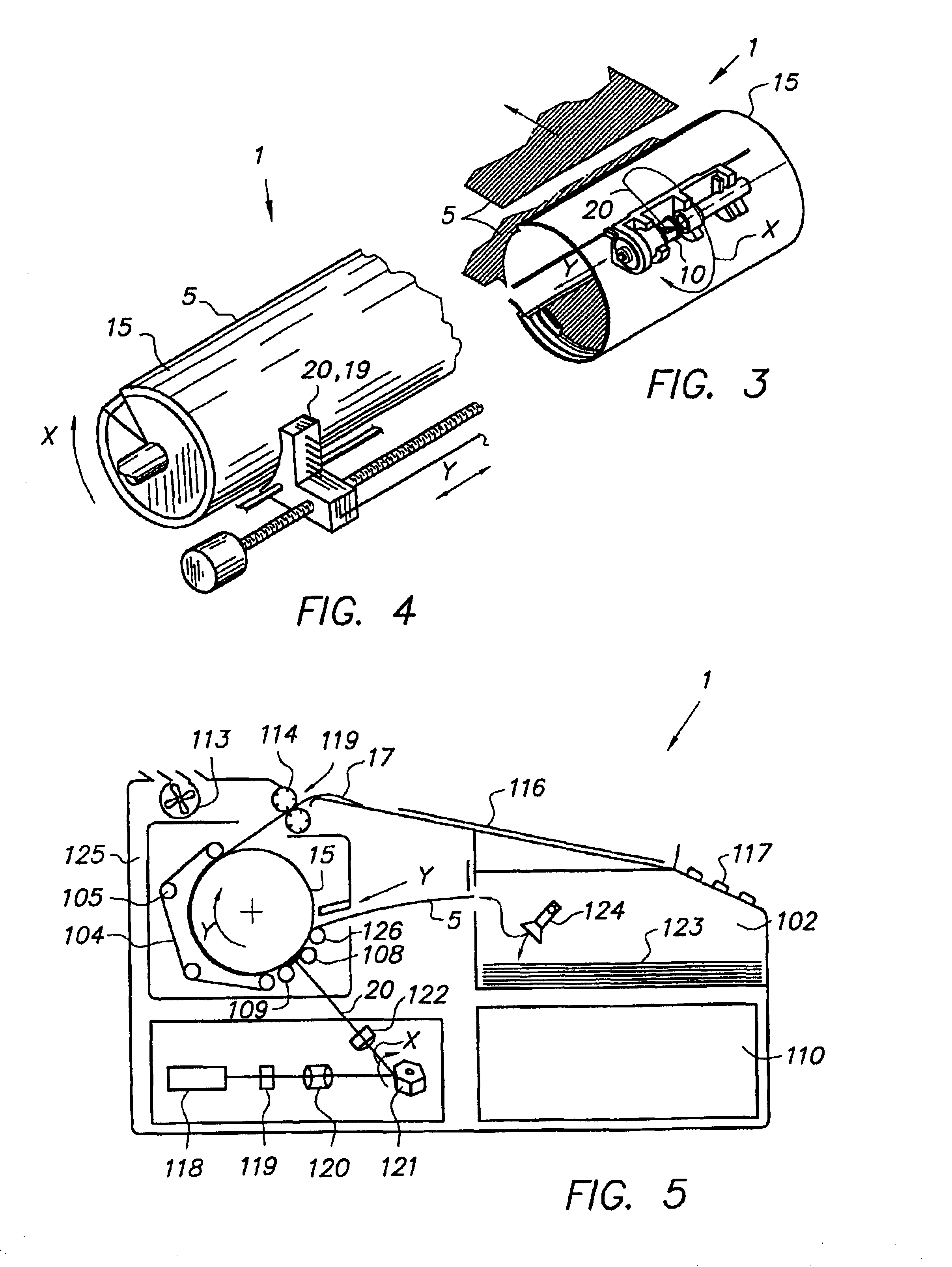
All experiments were carried out on an XTD-embodiment as shown in FIG. 6. Practical dimensions of this system (see also FIG. 8.1) included: the diameter D.sub.d of drum 15 being 70 mm, the width of the drum 15 being 250 mm and the width W.sub.m (46) of the thermographic material being 200 mm.

A preferred embodiment of the present invention was tested and evaluated extensively. The controllable parameters mentioned above, are summarized in the following paragraph.

1) Thermographic specifications of the substantially light-insensitive thermographic material m and of the IR-absorber (e.g. spectral bandwidth and sensitivity) were selected from a matrix of available values.

2) The temperature T.sub.p of the drum 15 was controlled in a range between 30.degree. C. and 150.degree. C., more preferably between 50.degree. C. and 120.degree. C., and set most typically at discrete values of 70, 75, 80, 85, 90 and 100.degree. C.

3) As regards the position of the thermographic material 5 with respect ...


PUM


Abstract

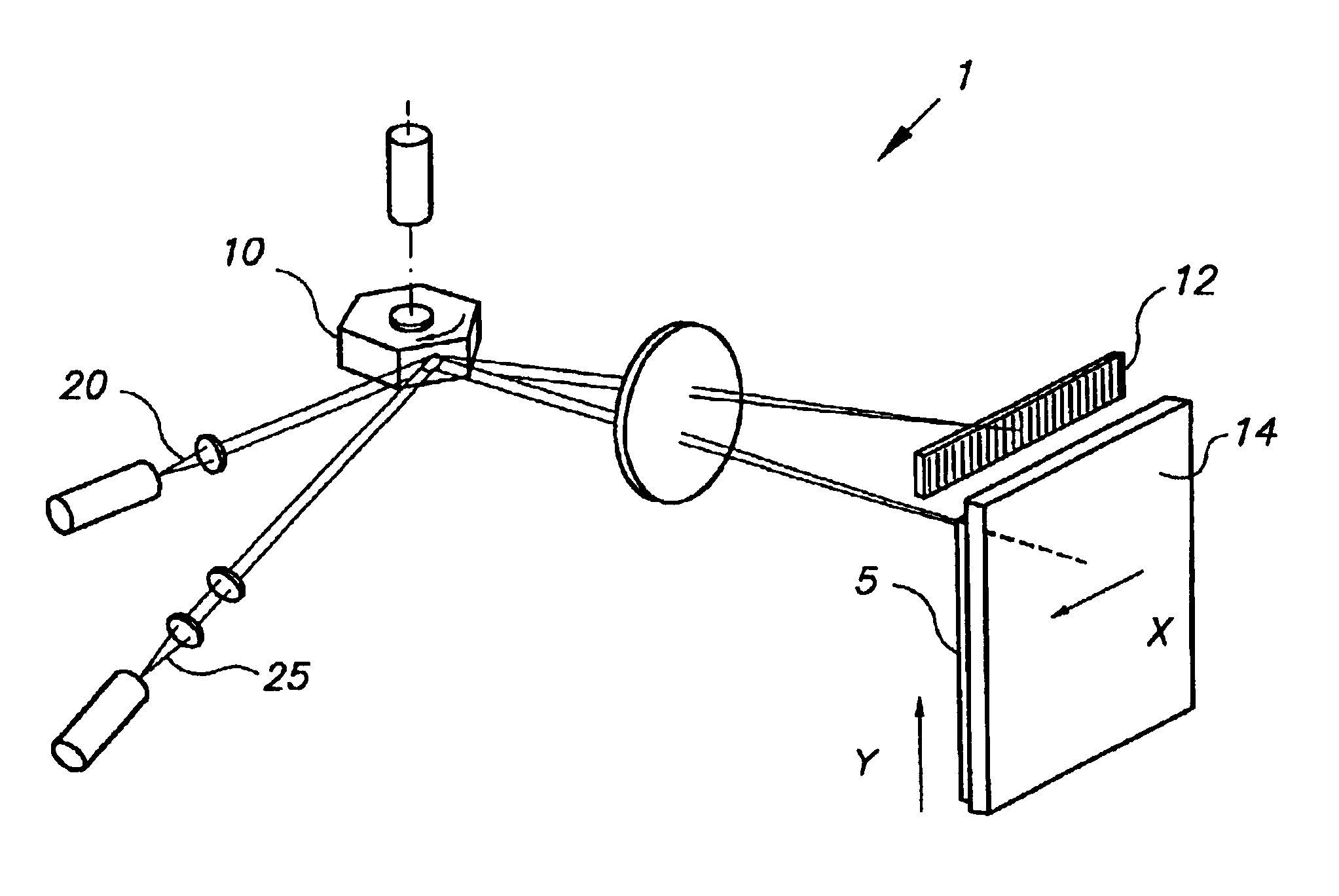
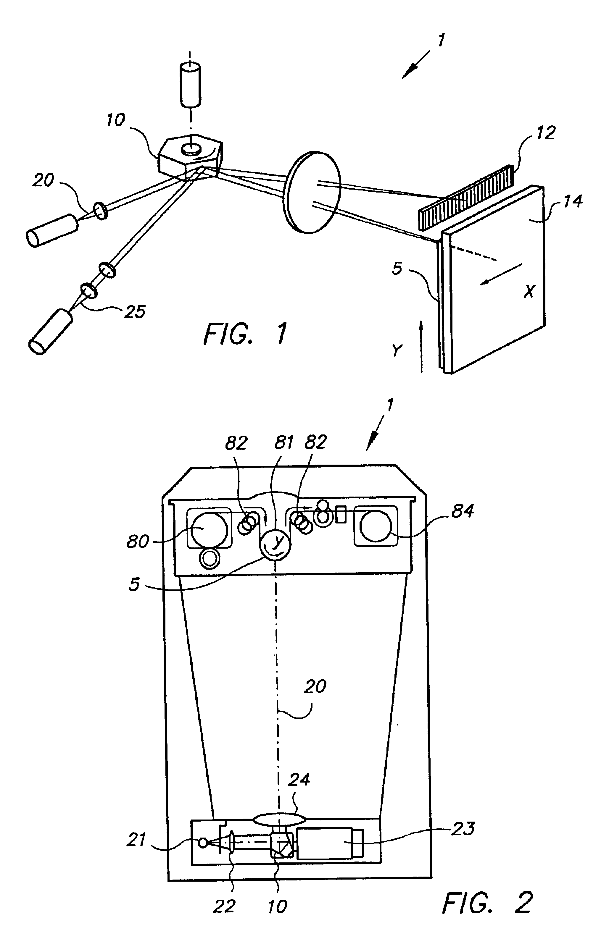
An apparatus for thermal recording an image in a substantially light-insensitive thermographic material m having a burning temperature Tb, the substantially light-insensitive thermographic material m comprising a thermosensitive element having a conversion temperature Tc, a support, and at least one light-to-heat conversion agent, comprises a means for generating a radiation beam 20 including wavelengths lambda absorbed by the light-to-heat conversion agent and an optical means of scanning a line 40 of the substantially light-insensitive thermographic material m with the radiation beam 20 at different positions thereon along a scanning direction at each point of time in a scanning cycle; and a method for recording information, comprising the steps of: providing an apparatus for thermal recording 1, the above-mentioned substantially light-insensitive thermographic material m (5); generating a radiation beam 20 including wavelengths lambda absorbed by the light-to-heat conversion agent and being modulated in accordance with the information to be recorded; scanning a line 40 of the substantially light-insensitive thermographic material m a first time with the radiation beam, thereby heating the line of the substantially light-insensitive thermographic material m to a first predetermined temperature T1 being above the conversion temperature Tc and below the burning temperature Tb of the substantially light-insensitive thermographic material m; re-scanning the same line of the substantially light-insensitive thermographic material m a plurality of times ns with the radiation beam being identically modulated in accordance with the information to be recorded.

Description

The present invention relates to a method and an apparatus for thermal recording by means of a flying spot.Thermal imaging or thermography is a recording process wherein images are generated by the use of imagewise modulated thermal energy. Most of the direct thermographic recording materials are of the chemical type. On heating to a certain conversion temperature, an irreversible chemical reaction takes place and a coloured image is produced. A particular interesting direct thermal imaging element uses an organic silver salt in combination with a reducing agent. Such combination may be imaged by a suitable heat source such as e.g. a thermal head, a laser etc.A black and white image can be obtained with such a material because under the influence of heat the silver ions are developed to metallic silver. However, it appears to be difficult to obtain a neutral black tone image. Furthermore, it appears to be difficult to obtain a sufficiently high density as required in certain applica...

Claims


Application Information

Patent Timeline
IPC IPC(8): B41J2/435B41J2/47G11B3/00G11B7/26G11C13/00G11B3/70G11B5/84B41J2/475
CPCB41J2/471B41J2/4753
Inventor RUDI, VANHOOYDONCK
Owner AGFA HEALTHCARE NV
Learn More