Method and device for the production of an essentially continous fine thread

a technology of essentially continous thread and production method, which is applied in the direction of filament/thread forming, spinnerette packs, non-woven fabrics, etc., can solve the problems of high energy expenditure, high cost, and high cost of hot air heating, and achieves reduced strength, reduced cost, and simple and economical methods.

Inactive Publication Date: 2004-10-05
GERKING LUDER
View PDF22 Cites 124 Cited by
  • Summary
  • Abstract
  • Description
  • Claims
  • Application Information

AI Technical Summary

Benefits of technology

The advantage of the present invention lies in that, in a simple and economical manner, very fine threads within a range of well below 10 .mu.m, mainly between 2 and 5 .mu.m, can be produced, which in the case of pure drawing for example by the melt-blow method can be accomplished only with hot gas (air) jets heated above melting point, and so requires considerably more energy. Moreover, the threads are not damaged in their molecular structure by excessive temperatures, which would lead to reduced strength, with the result that they can then often be rubbed out of a textile structure. Another advantage lies in that the threads are endless or quasi-endless and cannot protrude from a textile structure such as a non-woven fabric and come away as fuzz. The apparatus for carrying out the method according to the invention is simple. The spin holes of the spinning nozzle can be larger and so less susceptible to breakdowns, and the Laval nozzle cross-section in its precision does not need the narrow tolerances of the lateral air slots of the melt-blown method. For a given polymer one need only coordinate the melt temperature and the pressure in the chamber with each other, and with a given throughput per spin hole and the geometrical position of the spin holes relative to the Laval nozzle splitting occurs.
Practical examples of the invention are shown in the drawings and described in more detail in the description below. They show:
FIG. 1 a schematic sectional view of an apparatus for the manufacture of microthreads by means of cold gas jets by bursting of a melt stream into a plurality of single threads according to a first embodiment of the invention,
FIG. 2 a perspective partial view of the apparatus according to the invention in an embodiment with row nozzle and spin holes in nipple form for the manufacture of non-woven fabrics from microthreads, and
FIG. 3 a partial view in section of the spinning nozzle and Laval nozzle according to a third embodiment of the invention.
The nozzle orifice 3 is surrounded by an insulating assembly 9 which protects the nozzle orifice 3 against excessive heat losses due to the gas flow 5. In addition an electric band heating system 10 can be arranged between insulating assembly 9 and orifice 3.

Problems solved by technology

By mixing with the colder ambient air, there is cooling and solidification of these threads or fibres, for often, usually of course undesirably, the threads break.
The disadvantage of this melt-blown method is the high expenditure of energy to heat the hot air flowing at high speed, a limited throughput through the individual spin holes (even though these have been set increasingly closer together in the course of time, down to a spacing of below 0.6 mm with 0.25 mm in hole diameter), that with thread diameters of less than 3 .mu.m breaks occur, which leads to beads and protruding fibres in the subsequent textile composite, and that due to the high air temperature necessary to produce fine threads the polymers are thermally damaged well above the melt temperature.
They are expensive, operationally susceptible and tedious to clean.
If the pressure difference is so great that the strength of the thread envelope is no longer sufficient to hold together the interior, then the thread bursts.
Also the melt holes must not be cooled by the gas so greatly that the melt cools down too greatly, let alone already solidifies there.
Moreover, the threads are not damaged in their molecular structure by excessive temperatures, which would lead to reduced strength, with the result that they can then often be rubbed out of a textile structure.
As a result, cooling by the basically cold air / gas streams is delayed.

Method used


Image

  • Method and device for the production of an essentially continous fine thread
  • Method and device for the production of an essentially continous fine thread
  • Method and device for the production of an essentially continous fine thread

Examples


example 2

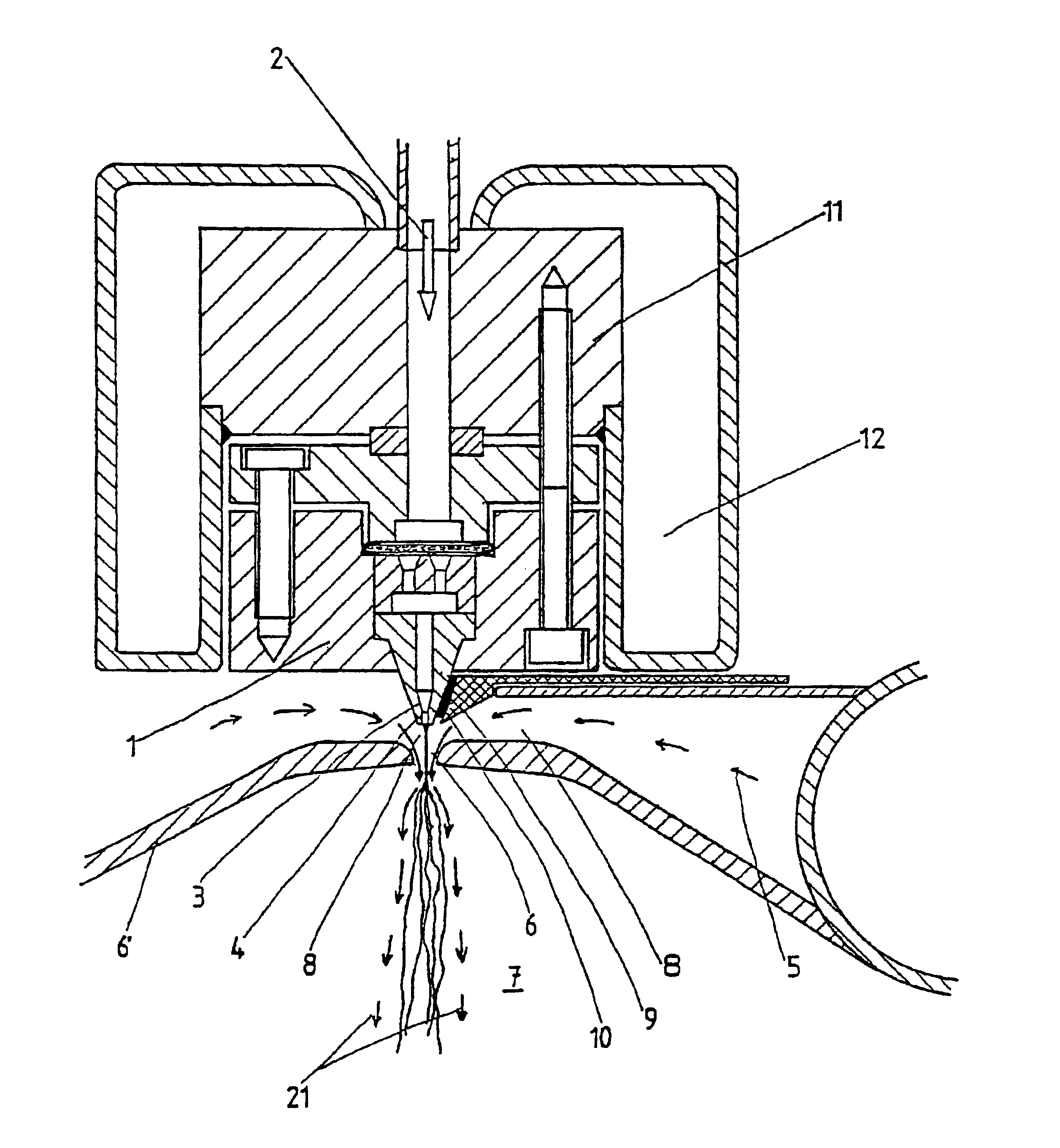
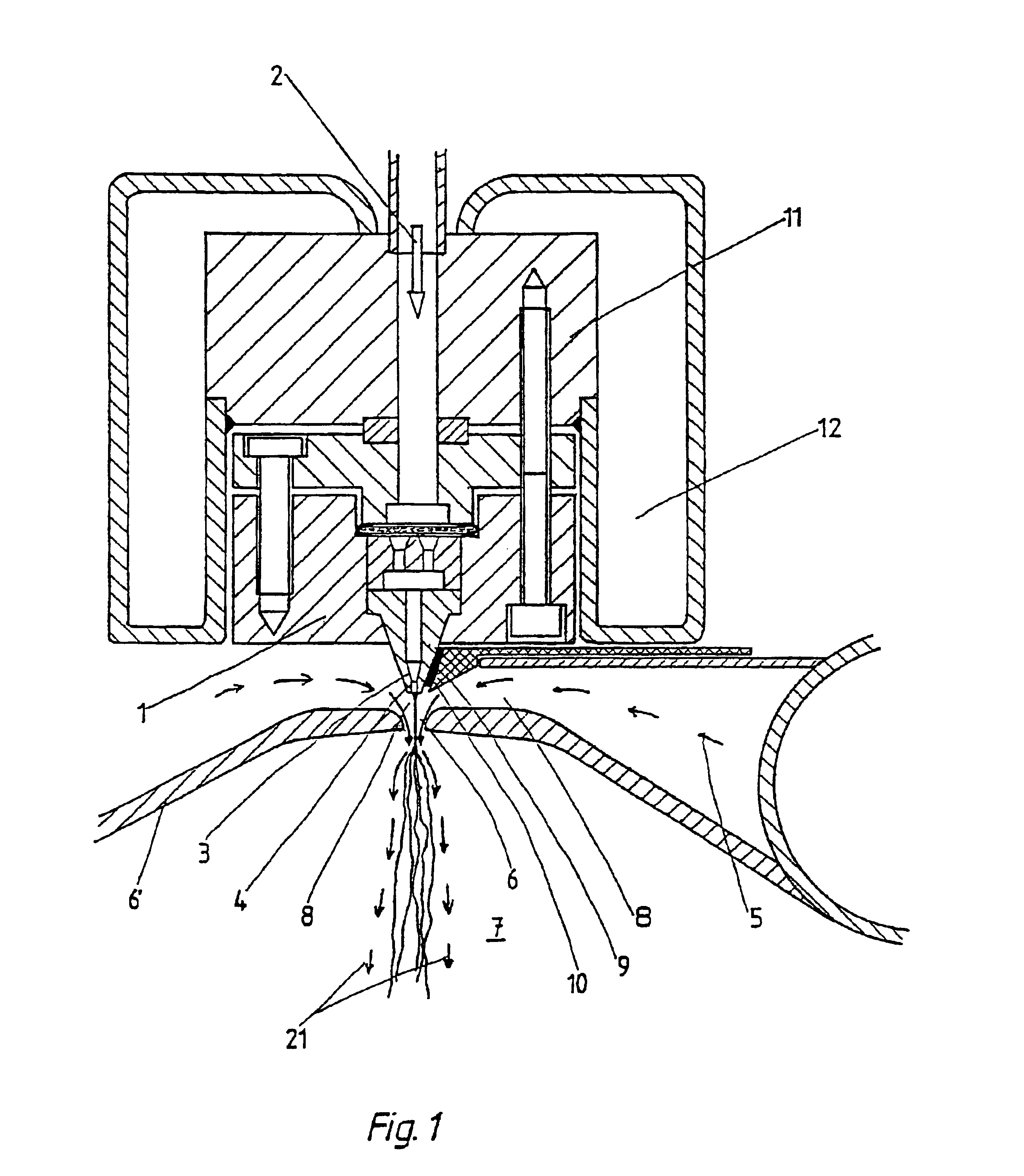
With the apparatus from example 1, polyamide 6 (PA6) with a relative viscosity .eta..sub.rel =2.4 was fed to a nozzle orifice 3 with 58 holes 4 at intervals of 1.5 mm and with a diameter of 0.4 mm. The distance from the outlet openings of the holes 4 to the narrowest cross-section of the Laval nozzle was 12.0 mm (the outlet openings ended 2.0 mm above the imaginary plane of the Laval nozzle plate). With a throughput per hole 4 of 0.25 g / min and a pressure in the chamber 8 of 0.02 bar above the environment, filaments with a mean diameter d.sub.50 of 4.1 .mu.m were produced.

example 3

With the apparatus from example 1, polypropylene (PP) with a MFI of 25 (230.degree. C., 2.16 kg) was fed to a nozzle orifice 3 with three holes 4 at intervals of 15 mm and with a diameter of 1.0 mm. Individual rotationally symmetrical Laval nozzles 6 were arranged in the Laval nozzle plate 3 coaxially with the three holes 4. The outlet openings of the holes 4 were arranged exactly at the level of the upper edge of the Laval nozzle plate and had a distance of 4.5 mm from the narrowest cross-section of the Laval nozzles 6. At a pressure in the chamber 8 of 0.75 bar above the environment 7 and with a throughput per hole 4 of 9.3 g / min, single filaments with a mean diameter d.sub.50 of 4.9 .mu.m were produced. In this case a theoretical thread count of 123 results.

Of interest in this manner of operation is the observation that the bursting point compared with example 1 has clearly shifted in the direction of the narrowest cross-section of the Laval nozzles 6. Whereas in the case of the ...


PUM

PropertyMeasurementUnit
diametersaaaaaaaaaa
diametersaaaaaaaaaa
diametersaaaaaaaaaa

Abstract

The invention relates to a method and a device for the production of essentially continuous fine threads made of meltable polymers. The polymer melt is spun from at least one spin hole (5) and the spun thread is attenuated using gas flows which are accelerated to achieve high speeds by means of a Laval nozzle (6). As a result of the specific geometry of the melt hole (4) and the position thereof in respect to the Laval nozzle (6), the temperature of the polymer melt, the throughout per spin hole and the pressures determining the velocity of the gas flow upstream and downstream from the Laval nozzle (6) are controlled in such a way that the thread reaches an internal hydrostatic pressure before solidifying, whereby said thread bursts into a plurality of fine threads.

Description

The invention concerns a method for the manufacture of very fine threads from melt-spinnable polymers and an apparatus for the manufacture thereofBACKGROUND OF THE RELATED TECHNOLOGYMicrothreads of this kind, but usually microfibres of finite length, have for many years been made by a hot-air spun-blown method, the so-called melt-blown method, and today there are different apparatuses for this. A common feature of all of them is that, in addition to a row of melt holes--several rows parallel to each other have also become known--hot air which draws the threads escapes. By mixing with the colder ambient air, there is cooling and solidification of these threads or fibres, for often, usually of course undesirably, the threads break. The disadvantage of this melt-blown method is the high expenditure of energy to heat the hot air flowing at high speed, a limited throughput through the individual spin holes (even though these have been set increasingly closer together in the course of tim...

Claims


Application Information

Patent Timeline
Patent Type & Authority Patents(United States)
IPC IPC(8): D04H3/02D01D4/02D04H3/16D01D5/08D01D4/00D04H3/03D01D5/098D04H1/724D04H1/732
CPCD01D4/025D01D5/0985D04H1/724B29C47/92D04H3/03D04H3/16D04H1/732B29C48/05
Inventor GERKING, LUDER
Owner GERKING LUDER
Why Eureka
Try Eureka