Process for producing optical element, optical element, optical films using optical element, and illuminator and liquid crystal display each using optical element or optical films

a technology of optical elements and optical films, applied in the direction of polarising elements, thin material processing, instruments, etc., can solve the problems of poor thickness precision and in-plane unevenness in optical properties, insufficient brightness improvement, and decrease in so as to improve brightness-improving characteristics and front-view hue/slant-view hue characteristics, the effect of reducing the cost of the film

Inactive Publication Date: 2004-10-12
NITTO DENKO CORP
View PDF8 Cites 4 Cited by
  • Summary
  • Abstract
  • Description
  • Claims
  • Application Information

AI Technical Summary

Benefits of technology

Furthermore, the process of the invention, in which one side orientation is conducted, is advantageous in that the amount of oriented substrates required is a half of that necessary in the related art process in which two oriented substrates are used to conduct both sides orientation, and thus attains decrease in the amount of industrial wastes. In addition, since high thickness precision and decreased product thickness can be attained, the cost of liquid crystal materials can be decreased. Still a further advantage of the invention is as follows. For the spread of a wavelength range of a dye-containing system in both-sides orientation embodiment, a certain extent of layer thickness is required for the reason that the rate of crosslinking reaction should be controlled based on light absorption by the dye. In contrast, according to the process of the present invention, orientation properties and thickness precision are improved, and hence, brightness-improving characteristics and front view hue / slant view hue characteristics are improved. Consequently, the optical element can be used in a wider wavelength range with the necessary and minimum thickness, whereby decrease in film cost can be attained. Moreover, roll-to-roll production is possible and improvement in production efficiency can hence be attained.
is as follows. For the spread of a wavelength range of a dye-containing system in both-sides orientation embodiment, a certain extent of layer thickness is required for the reason that the rate of crosslinking reaction should be controlled based on light absorption by the dye. In contrast, according to the process of the present invention, orientation properties and thickness precision are improved, and hence, brightness-improving characteristics and front view hue / slant view hue characteristics are improved. Consequently, the optical element can be used in a wider wavelength range with the necessary and minimum thickness, whereby decrease in film cost can be attained. Moreover, roll-to-roll production is possible and improvement in production efficiency can hence be attained.
In the process for producing an optical element, the temperature during the irradiation with radiation is preferably 40.degree. C. or higher. By regulating the temperature during the irradiation with radiation to 40.degree. C. or higher, the liquid crystal material can be polymerized and cured in a satisfactorily oriented state. The temperature during the irradiation with radiation is more preferably from about 50 to 90.degree. C.
In the process for producing an optical element, the gas comprising oxygen preferably has an oxygen concentration of 0.5 vol % or higher. Air is preferably used as the gas.
The irradiation with radiation in the process for optical-element production is preferably conducted at an intensity of from 10 to 1,000 mW / cm.sup.2. According to the present invention, when an ultraviolet source (365 nm) is used at an irradiation intensity within the above range, an optical element can be produced through exposure in an extremely short period of time of from 0.1 second to 2 minutes. Thus, optical elements can be produced at an extremely high efficiency. The irradiation intensity is more preferably from 50 to 500 mW / cm.sup.2.
In the case where ultraviolet rays are used as the radiation in the process for producing an optical element, the mixed solution preferably contains a polymerization initiator in an amount of from 0.5 to 10% by weight based on the weight of the sum of the polymerizable nematic liquid crystal compound and the polymerizable chiral reagent. In order to polymerize the liquid crystal mixture by ultraviolet irradiation, the mixed solution should contain a polymerization initiator. The amount of the initiator used is preferably in the above range in order to obtain an optical element comprising a polymeric liquid crystal layer having a helically twisted molecular structure, that can be used in a wider wavelength range. The amount of the polymerization initiator used is preferably from 1 to 9% by weight, more preferably from 3 to 7% by weight.

Problems solved by technology

However, the process disclosed in this publication, in which a liquid crystal mixture sandwiched between two oriented substrates is polymerized, involves poor thickness precision and in-plane unevenness in optical properties due to the poor thickness precision.
As a result, this process has disadvantages that brightness improvement is insufficient and front-view hue / slant-view hue characteristics decrease.
In addition, there is a problem that a large amount of industrial wastes is unavoidable because of the necessity of oriented substrates on both sides of the liquid crystal mixture.
Such a large product thickness results in poor thickness precision, which causes in-plane unevenness in optical properties.
The related art technique hence has disadvantages that brightness improvement is insufficient and front view hue / slant view hue characteristics decrease.
Still another problem is that the large product thickness increases the material cost.
This process hence has a considerably poor production efficiency.
In this case, however, orientation properties of the liquid crystal become insufficient and this causes in-plane unevenness in optical properties.
This technique hence has the disadvantages that brightness improvement is insufficient and front view hue / slant view hue characteristics decrease.
This makes it difficult to conduct roll-to-roll production and the process hence has a considerably low production efficiency.

Method used


Image

  • Process for producing optical element, optical element, optical films using optical element, and illuminator and liquid crystal display each using optical element or optical films
  • Process for producing optical element, optical element, optical films using optical element, and illuminator and liquid crystal display each using optical element or optical films

Examples


production example 2

Preparation of Mixed Solution

A monofunctional, acrylic, nematic liquid crystal monomer showing liquid crystal properties in the temperature range of from 80 to 210.degree. C. was mixed with a bifunctional acrylic chiral reagent in a ratio of 95:5 by weight. This mixture was dissolved in a solvent (methyl ethyl ketone) so as to achieve a concentration of about 33% by weight. A polymerization initiator was added thereto in an amount of 5% by weight based on the weight of the sum of the monomer and the chiral reagent. Thus, a mixed solution A was prepared.

production example 3

Preparation of Mixed Solution

A bifunctional, acrylic, nematic liquid crystal monomer showing liquid crystal properties in the temperature range of from 80 to 210.degree. C. was mixed with a bifunctional acrylic chiral reagent in a ratio of 95:5 by weight. This mixture was dissolved in a solvent (methyl ethyl ketone) so as to acheive a concentration of about 33% by weight. A polymerization initiator was added thereto in an amount of 5% by weight based on the weight of the sum of the monomer and the chiral reagent. Thus, a mixed solution B was prepared.

example 1

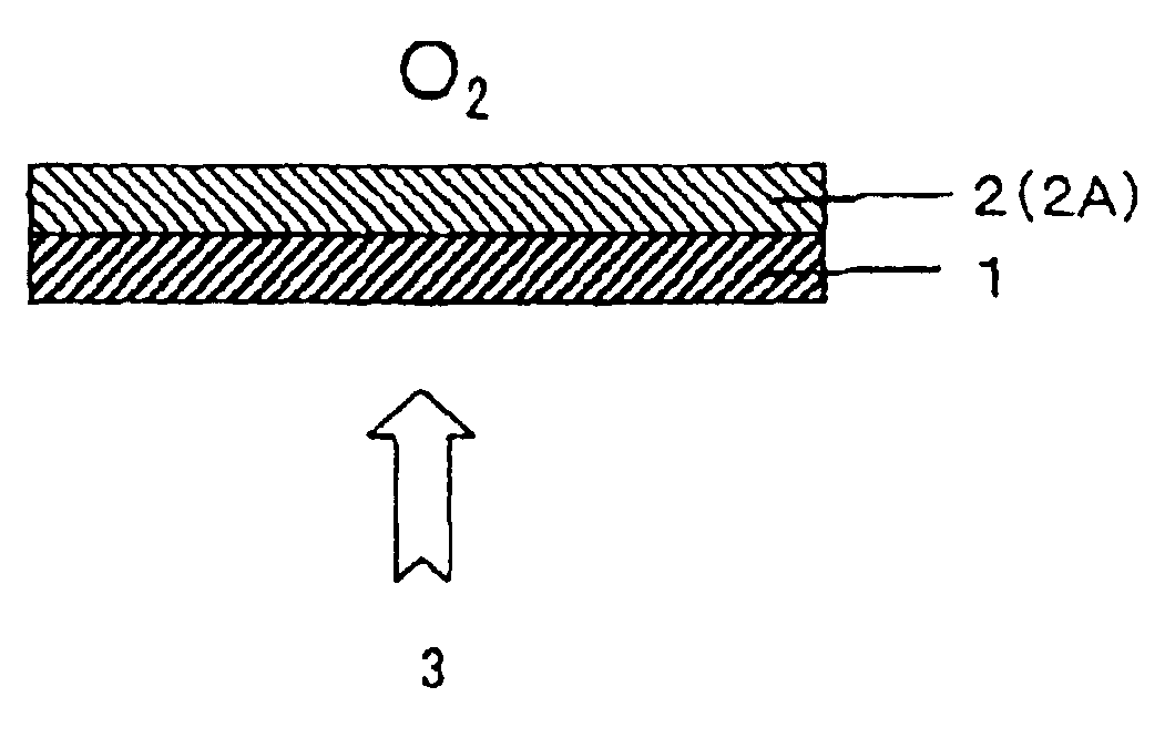
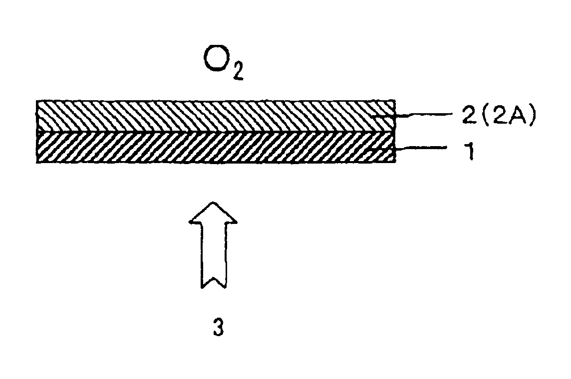
The mixed solution B was applied to the oriented substrate (orientation treatment side) and the solvent was removed by volatilization. Thereafter, the coated substrate was heated to 120.degree. C. to align the liquid crystal and then irradiated, from the oriented substrate side, with 100 mW / cm.sup.2 ultraviolet rays at 60.degree. C. in air for 2 seconds using a metal halide lamp. Thus, a thin film was obtained. This film had a thickness of 5 .mu.m.


PUM

PropertyMeasurementUnit
temperatureaaaaaaaaaa
thicknessaaaaaaaaaa
thicknessaaaaaaaaaa

Abstract

A process for producing an optical element which comprises a polymeric liquid crystal layer having a helically twisted molecular structure and has satisfactory thickness precision and satisfactory optical properties. The process comprises applying a mixed solution containing a polymerizable nematic liquid crystal compound and a polymerizable chiral reagent to an oriented substrate, followed by drying, to orient the liquid crystal compound; and irradiating the mixed solution applied with radiation from the oriented substrate side while maintaining the mixed solution in contact with a gas comprising oxygen to thereby polymerize and cure the mixed solution.

Description

The present invention relates to a process for producing an optical element comprising a polymeric liquid crystal layer having a helically twisted molecular structure. The invention further relates to an optical element obtained by the process, optical films using the optical element, and an illuminator and a liquid crystal display each using the optical element or optical films.DESCRIPTION OF THE RELATED ARTConventional processes for producing an optical element comprising a polymeric liquid crystal layer having a helically twisted molecular structure include, for example, a process which comprises sandwiching a liquid crystal mixture comprising a polymerizable liquid crystal monomer and a chiral monomer between two parallel oriented substrates, and polymerizing and curing the mixture with ultraviolet rays or the like to produce a cholesteric polarizer having a helically twisted molecular structure (see Japanese Paten Laid-Open No. 6-281814). However, the process disclosed in this ...

Claims


Application Information

Patent Timeline
Patent Type & Authority Patents(United States)
IPC IPC(8): G02B5/30G02F1/13G02F1/13363
CPCG02B5/3016Y10T428/1036C09K2323/03G02F1/13
Inventor KAWAMOTO, IKUOMOTOMURA, HIRONORISHIRAOGAWA, MIKI
Owner NITTO DENKO CORP
Why Eureka
Try Eureka