Zoom lens, and electronic imaging system using the same

a technology of electronic imaging system and zoom lens, which is applied in the field of zoom lens and electronic imaging system, can solve the problems of difficult to make the second lens group itself thin, difficult to make aberration correction, and the thickness of the optical system that is the bottleneck in reducing the depth dimension of the camera, so as to reduce simplify the layout of the camera. , the effect of reducing the size of the zoom lens

Inactive Publication Date: 2004-10-26
OLYMPUS OPTICAL CO LTD +1
View PDF6 Cites 18 Cited by
  • Summary
  • Abstract
  • Description
  • Claims
  • Application Information

AI Technical Summary

Benefits of technology

In view of such problems as referred to above, the primary object of the invention is to thoroughly slim down a video or digital camera by singling out a zoom mode or zoom construction wherein a reduced number of lens elements are used to reduce the size of a zoom lens and s...

Problems solved by technology

The gravest bottleneck in diminishing the depth dimension of cameras is the thickness of an optical system, especially a zoom lens system from the surface located nearest to its object side to an image pickup plane.
Thus, it is not only difficult to make the second lens gr...

Method used


Image

  • Zoom lens, and electronic imaging system using the same
  • Zoom lens, and electronic imaging system using the same
  • Zoom lens, and electronic imaging system using the same

Examples


examples 1 to 8

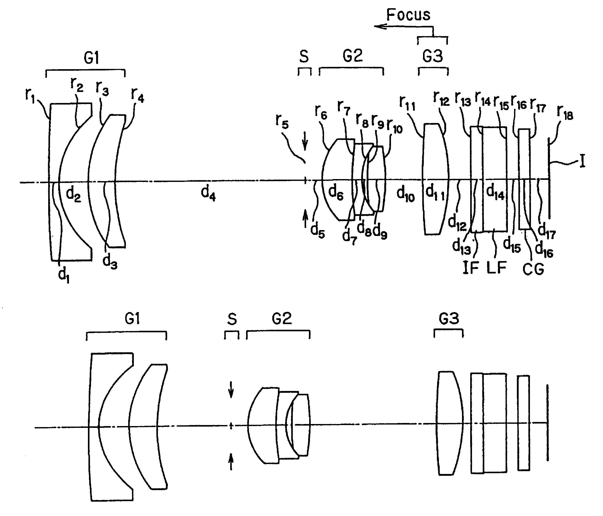
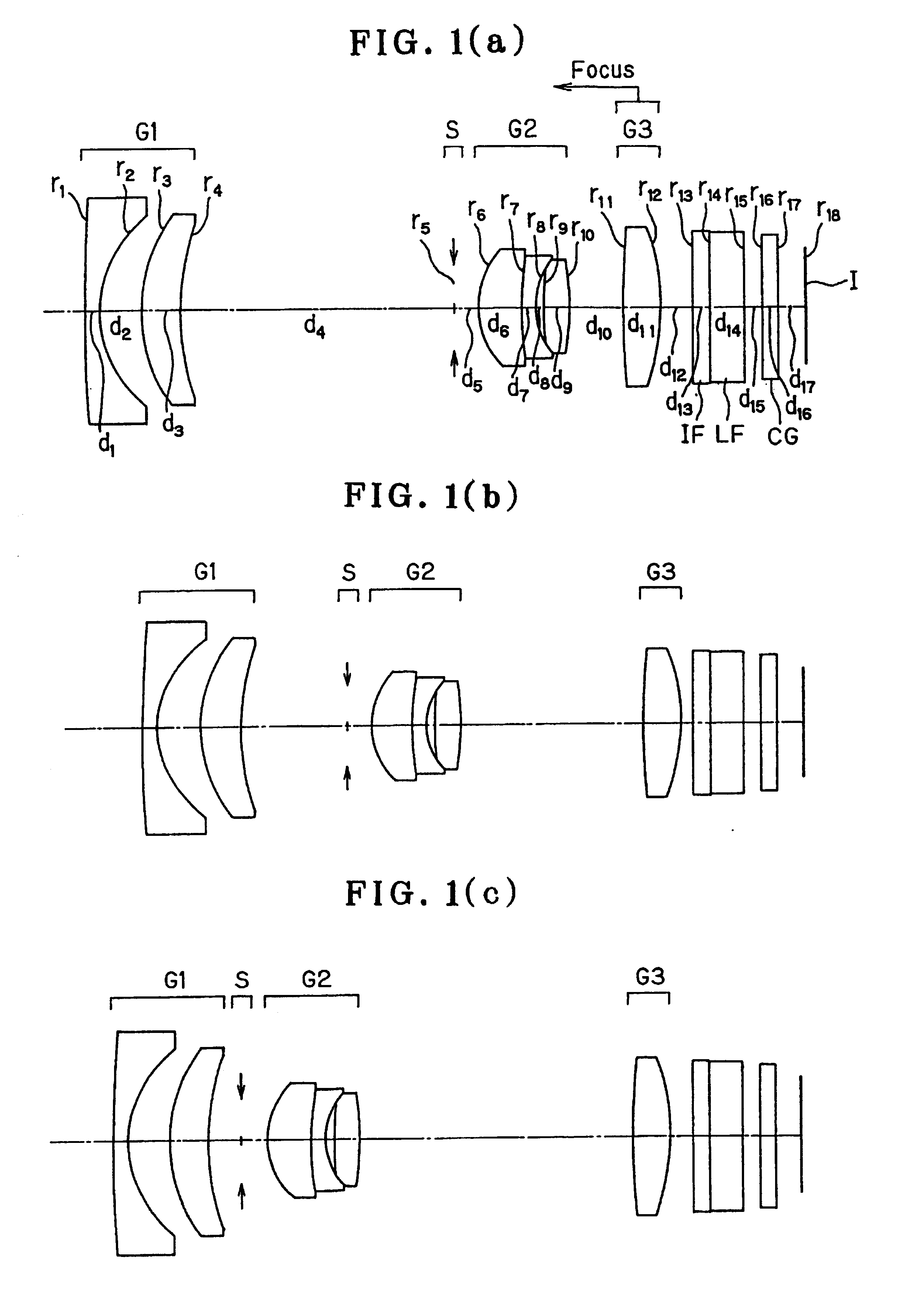
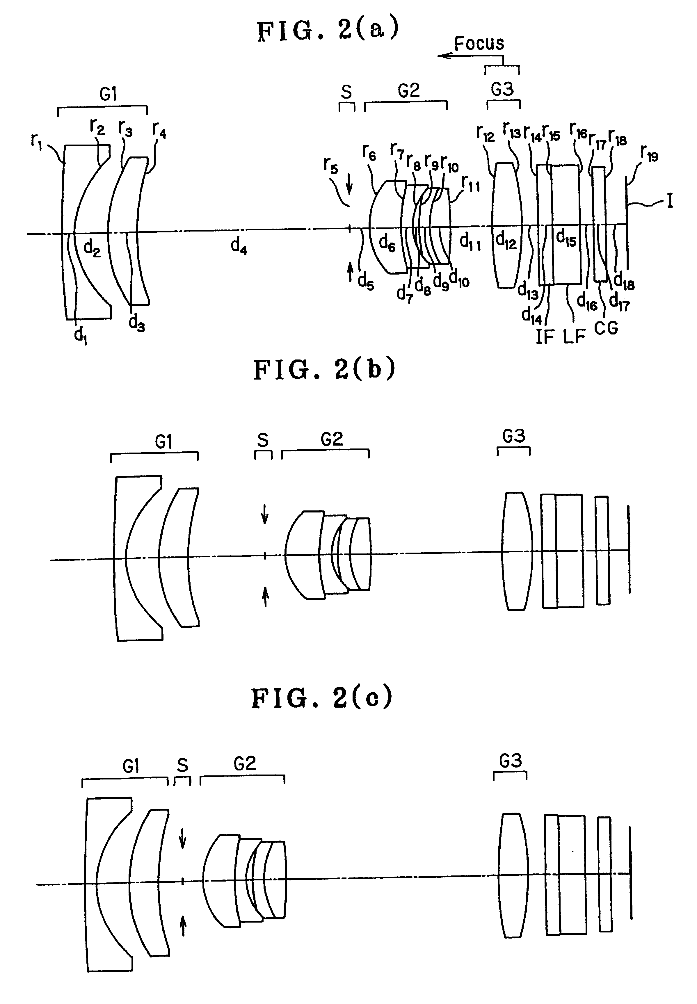
of the zoom lens used with the electronic imaging system of the present invention are now explained. Sectional lens configurations of these examples at the wide-angle end (a), in an intermediate state (b) and at the telephoto end (c) upon focused on an object point at infinity are shown in FIGS. 1 through 7 wherein G1 represents a first lens group, S a stop, G2 a second lens group, G3 a third lens group, capital IF a an infrared cut absorption filter, capital LF a low-pass filter, CG a cover glass for a CCD that is an electronic image pickup device located on the image side of the zoom lens, and I the image plane of CCD. Instead of the infrared cut absorption filter IF, it is acceptable to use a transparent plane plate with a near-infrared sharp cut coat applied on the entrance surface or a low-pass filter LF that is directly provided with a near-infrared sharp cut coat.

EXAMPLE 1

As shown in FIGS. 1(a), 1(b) and 1(c), Example 1 is directed to a zoom lens made up of a first lens group...

example 1

r.sub.1 = 79.4668 d.sub.1 = 0.7000 n.sub.d1 = 1.74320 .nu..sub.d1 = 49.34 r.sub.2 = 5.0248(Aspheric) d.sub.2 = 2.0000 r.sub.3 = 7.7722 d.sub.3 = 1.8000 n.sub.d2 = 1.84666 .nu..sub.d2 = 23.78 r.sub.4 = 12.8300 d.sub.4 = (Variable) r.sub.5 = .infin. (Stop) d.sub.5 = 1.2000 r.sub.6 = 3.8190(Aspheric) d.sub.6 = 2.0000 n.sub.d3 = 1.80610 .nu..sub.d3 = 40.92 r.sub.7 = 14.0000 d.sub.7 = 0.7000 n.sub.d4 = 1.84666 .nu..sub.d4 = 23.78 r.sub.8 = 3.2333 d.sub.8 = 0.4000 r.sub.9 = 13.6941 d.sub.9 = 1.3000 n.sub.d5 = 1.69350 .nu..sub.d5 = 53.21 r.sub.10 = -13.6343 d.sub.10 = (Variable) r.sub.11 = 41.4339 d.sub.11 = 1.8000 n.sub.d6 = 1.48749 .nu..sub.d6 = 70.23 r.sub.12 = -10.8130 d.sub.12 = (Variable) r.sub.13 = .infin. d.sub.13 = 0.8000 n.sub.d7 = 1.51633 .nu..sub.d7 = 64.14 r.sub.14 = .infin. d.sub.14 = 1.5000 n.sub.d8 = 1.54771 .nu..sub.d8 = 62.84 r.sub.15 = .infin. d.sub.15 = 0.8000 r.sub.16 = .infin. d.sub.16 = 0.7500 n.sub.d9 = 1.51633 .nu..sub.d9 = 64.14 r.sub.17 = .infin. d.sub.17 = 1.209...

example 2

r.sub.1 = 74.8530 d.sub.1 = 0.7000 n.sub.d1 = 1.74320 .nu..sub.d1 = 49.34 r.sub.2 = 4.9774(Aspheric) d.sub.2 = 2.0000 r.sub.3 = 7.9510 d.sub.3 = 1.8000 n.sub.d2 = 1.84666 .nu..sub.d2 = 23.78 r.sub.4 = 13.0310 d.sub.4 = (Variable) r.sub.5 = .infin. (Stop) d.sub.5 = 1.2000 r.sub.6 = 3.7607(Aspheric) d.sub.6 = 2.0000 n.sub.d3 = 1.80610 .nu..sub.d3 = 40.92 r.sub.7 = 10.0000 d.sub.7 = 0.7000 n.sub.d4 = 1.84666 .nu..sub.d4 = 23.78 r.sub.8 = 3.0755 d.sub.8 = 0.4000 r.sub.9 = 7.5308 d.sub.9 = 0.7000 n.sub.d5 = 1.80610 .nu..sub.d5 = 40.92 r.sub.10 = 5.0000 d.sub.10 = 1.3000 n.sub.d6 = 1.69350 .nu..sub.d6 = 53.21 r.sub.11 = -28.2295 d.sub.11 = (Variable) r.sub.12 = 21.7265 d.sub.12 = 1.8000 n.sub.d7 = 1.48749 .nu..sub.d7 = 70.23 r.sub.13 = -13.6621 d.sub.13 = (Variable) r.sub.14 = .infin. d.sub.14 = 0.8000 n.sub.d8 = 1.51633 .nu..sub.d8 = 64.14 r.sub.15 = .infin. d.sub.15 = 1.5000 n.sub.d9 = 4.54771 .nu..sub.d9 = 62.84 r.sub.16 = .infin. d.sub.16 = 0.8000 r.sub.17 = .infin. d.sub.17 = 0.7500 ...


PUM


Abstract

The invention provides a zoom lens that comprises a reduced number of lens elements, is compact and simplified, and has high image-formation capability, thereby achieving thorough size reductions in video cameras or digital cameras, and an electronic imaging system using the same. The zoom lens comprises a first lens group G1 of negative refracting power, a second lens group G2 of positive refracting power and a third lens group G3 of positive refracting power. Upon zooming from the wide-angle end to the telephoto end of the zoom lens, the second lens group G2 moves toward the object side alone of the zoom lens, and the third lens group G3 moves while the spacing between the third lens group G3 and the second lens group G2 varies. The second lens group G2 is composed of a front subgroup and a rear subgroup. The front subgroup is composed of a doublet component consisting of, in order from its object side, a positive lens element having an aspheric surface and a negative lens element, and the rear subgroup is composed of one positive lens component. The third lens group G3 then satisfies condition (1) with respect to the axial radii of curvature of the surfaces located nearest to the object and image sides of the third lens group G3.

Description

This application claims benefits of Japanese Application No. 2001-351624 filed in Japan on Nov. 16, 2001, the contents of which are incorporated by this reference.BACKGROUND OF THE INVENTIONThe present invention relates generally to a zoom lens and an electronic imaging system, and more particularly to a zoom lens, the depth dimension of which is diminished by providing some contrivances to an optical system portion such as a zoom lens and an electronic imaging system using the same, such as a video or digital camera. According to the present invention, the zoom lens is also designed to be capable of rear focusing.In recent years, digital cameras (electronic cameras) have received attention as cameras of the next generation, an alternative to silver-halide 35 mm-film (usually called Leica format) cameras. Currently available digital cameras are broken down into some categories in a wide range from the high-end type for commercial use to the portable low-end type.In view of the categ...

Claims


Application Information

Patent Timeline
IPC IPC(8): G02B15/177G02B5/22G02B5/20G02B5/26G02B13/18G02B15/20H04N5/225H04N101/00
CPCG02B13/18G02B15/177G02B15/20H04N5/225G02B5/22G02B5/26G02B5/20G02B15/143507H04N23/00
Inventor MIHARA, SHINICHI
Owner OLYMPUS OPTICAL CO LTD
Why Eureka
Try Eureka