Injection molding machine with a linear motor

Inactive Publication Date: 2004-11-23
MANNESMANN PLASTICS MACHINERY
View PDF12 Cites 13 Cited by
  • Summary
  • Abstract
  • Description
  • Claims
  • Application Information

AI Technical Summary

Problems solved by technology

The disadvantage of this design is the relatively weak closing force which can be exerted by the linear motor.
The efficiency of linear motors is especially poor at low speeds and when no motion at all is occurring.
This leads to an uneconomically large installation cost for the linear motor and for the converter required to operate the drive.
It must also be expected that the amount of energy consumed will be uneconomical in comparison with rotating motors.
This disadvantage cannot be avoided by the use of a divided end plate provided with electromagnets to build up the closing force.
The expansion of the tie bars leads in this solution to a considerable widening of the air gap and thus to a drastic drop in the amount of force which can be transmitted.
The only way to compensate for this is to increase the size of t

Method used


Image

  • Injection molding machine with a linear motor
  • Injection molding machine with a linear motor
  • Injection molding machine with a linear motor

Examples


Embodiment Construction

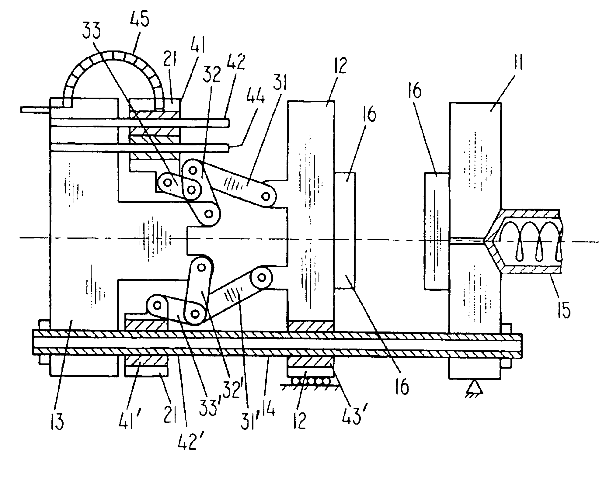
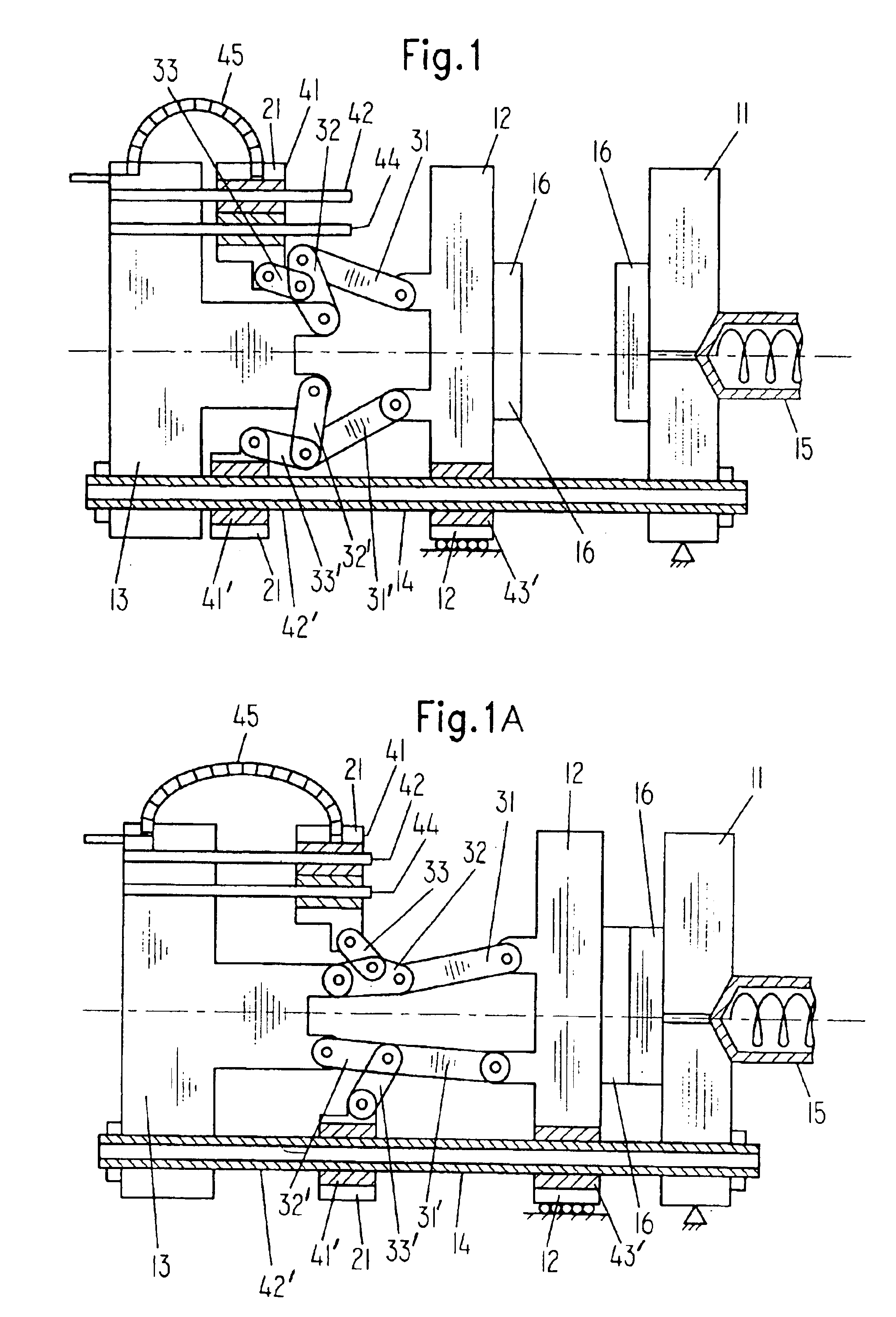
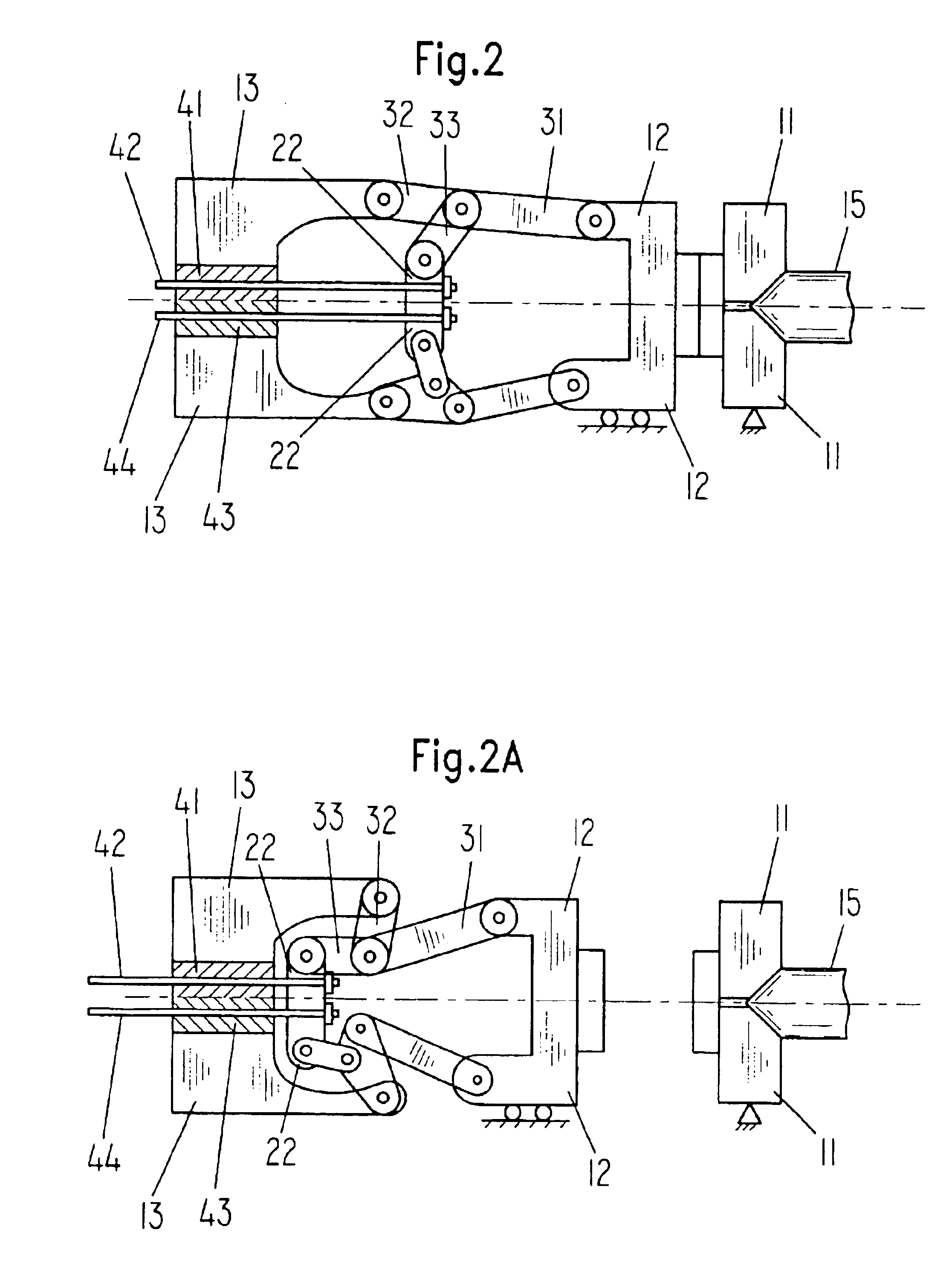
FIGS. 1 and 2 show an injection molding machine with a stationary mold clamping plate 11, a movable mold clamping plate 12, and an end plate 13. An injection cylinder 15 is mounted on the stationary mold clamping plate. The mold 16 is attached to the mold clamping plates 11, 12.

FIG. 1 shows an injection-molding machine with a force transmission element, which is designed as an actuating frame 21.

The movable mold plate 12 can be seen in the open position in FIG. 1. Between the movable mold clamping plate 12 and the actuating frame 21, in the upper part of the figure is a five-point toggle lever 31-33.

The inductor combs 41, 43 of a first double comb linear motor are arranged in a pairwise manner in the actuating frame. The reaction rails 42, 44 are connected to the end plate 13.

To supply energy and cooling water, the actuating frame 21 is connected by way of a drag line 45 to the end plate.

The movable mold clamping plate can be seen in the closed position in FIG. 1A. Between the mold ...


PUM

PropertyMeasurementUnit
Forceaaaaaaaaaa
Energyaaaaaaaaaa

Abstract

The invention pertains to a closing device in the form of an injection-molding machine for plastics with a stationary mold clamping plate and a movable mold clamping plate, which can be operated by a linear motor. At least one linear motor (41, 42) is connected to a force transmission element (21, 22) which is connected to a lever mechanism (31-33).

Description

1. Field of the InventionThe invention pertains to a closing device in the form of an injection molding machine for plastics with a stationary mold clamping plate and with a movable mold clamping plate, which can be operated by a linear motor.2. Description of the Related ArtA closing unit in which the end plate cooperates with the plunger to form a linear motor is known from DE 37 15 161 A1. The 3-phase windings are provided in the end plate and the plunger is designed as a "rotor" rail.The disadvantage of this design is the relatively weak closing force which can be exerted by the linear motor. In another embodiment, therefore, an electromagnet is provided to produce the required closing pressure; when current is flowing through this electromagnet, it induces a force on the plunger directed toward the mold.The efficiency of linear motors is especially poor at low speeds and when no motion at all is occurring. In the design described in the previously cited document, however, the m...

Claims


Application Information

Patent Timeline
IPC IPC(8): B29C45/66B29C45/17
CPCB29C45/1761B29C45/661B29C2045/7271B29C2045/1793
Inventor FISCHBACH, GUNTHER
Owner MANNESMANN PLASTICS MACHINERY
Why Eureka
Try Eureka