Fuel injector nozzle adapter

a technology of fuel injector and nozzle, which is applied in the direction of combustion air/fuel air treatment, machine/engine, secondary air addition to fuel, etc., can solve the problems of increasing the difficulty of installing a nitrous oxide system on the engine, fuel may not be evenly distributed to the cylinders by the dry intake plenum, and engine designs are difficult to modify for specialty purposes using conventional modification techniques and devices

Inactive Publication Date: 2005-01-04
HOLLEY PERFORMANCE PRODUCTS
View PDF34 Cites 26 Cited by
  • Summary
  • Abstract
  • Description
  • Claims
  • Application Information

AI Technical Summary

Benefits of technology

The first and second outlets may be on opposite sides of the fuel injector passage, or they may

Problems solved by technology

Although this evolution has made engines more efficient and has often resulted in modest power increases, the resulting engine designs have proven to be difficult to modify for specialty purposes using conventional modification techniques and devices.
Although multipoint fuel injection systems increase the combustion efficiency of the engine, and provide the potential for increased power, they have increased the difficulty of installing a nitrous oxide system on the engine.
The problem stems largely from the “dry” intake plenums used with multipoint fuel injected engines.
As such, when nitrous oxide and fuel are supplied at a central location along the air inlet as they are with carbureted engines and single-point fuel injected engines, the fuel may not be evenly distributed to the cylinders by the dry intake plenums.
Such condition causes some cylinders to run excessively rich and others excessively lean resulting in backfires in the intake manifold and/or engine failure.
Other problems may also exist when using a single source of nitrous oxide with a modern multipoint fuel injected engine.
This solution, however, has several limitations.
Two of the more problematic factors are the intake plenum thickness and intake plenum material.
Even under the best of circumstances, that is, when the intake plenum is aluminum and thick enough to engage a threaded fastener, the installation process is labor intensive and requires removal of the intake plenum to avoid contaminating the engine with debris created d

Method used


Image

  • Fuel injector nozzle adapter
  • Fuel injector nozzle adapter
  • Fuel injector nozzle adapter

Examples


Embodiment Construction

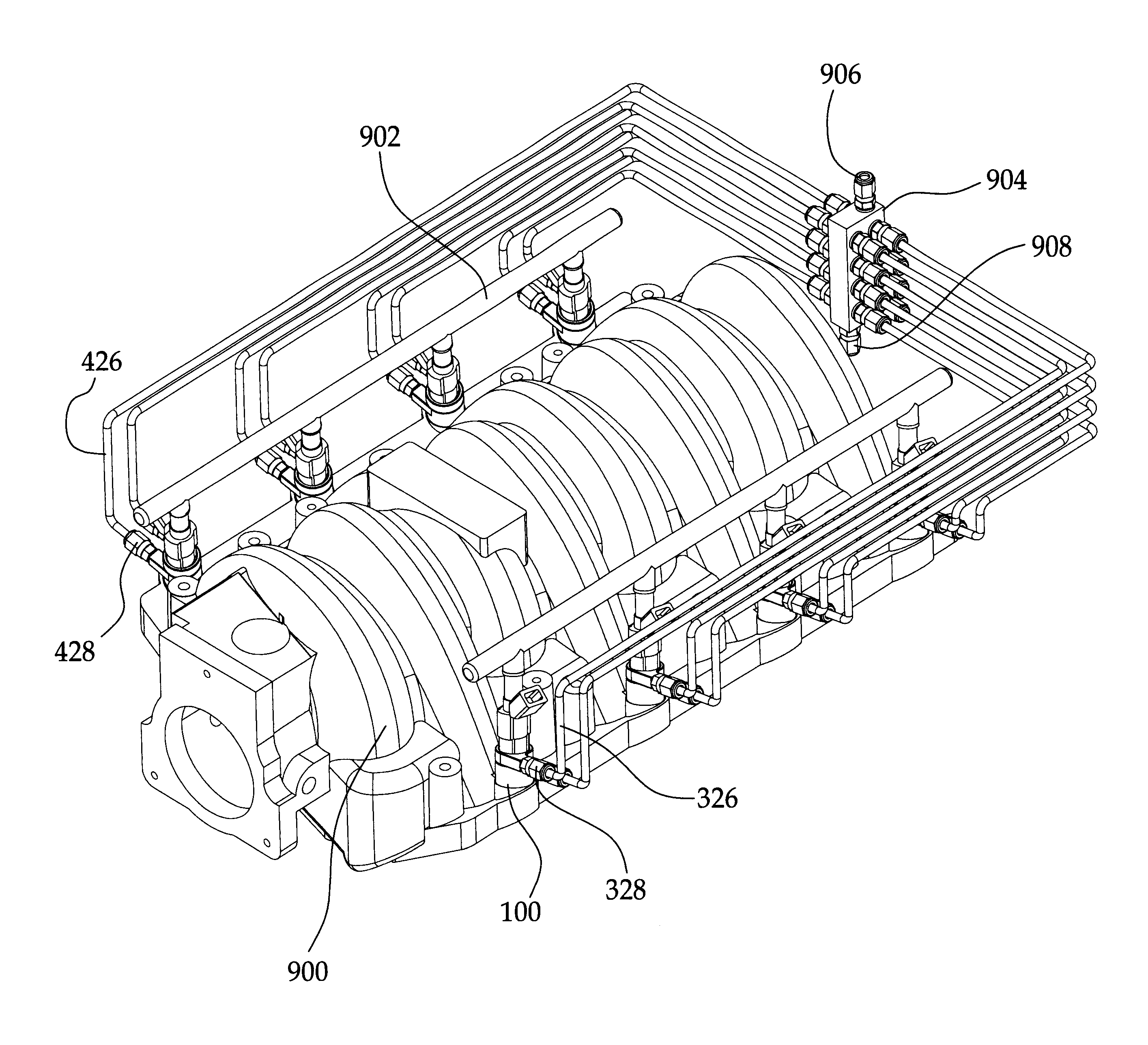
The term “engine,” as used herein, refers to any type of internal combustion engine, such as two- and four-stroke reciprocating piston engines and rotary engines (e.g., Wankel-type engines) having one or more cylinders or combustion chambers. Such engines may be used to propel vehicles, such as automobiles, industrial equipment, watercraft and aircraft, and may be used in various stationary applications, such as power generation, pumping, and other industrial uses. Although the present invention is particularly suited to provide increased power in automotive applications, embodiments of the invention may be used to provide benefits in any other application when an intermittent or continuous increase in power output is desired for an internal combustion engine.

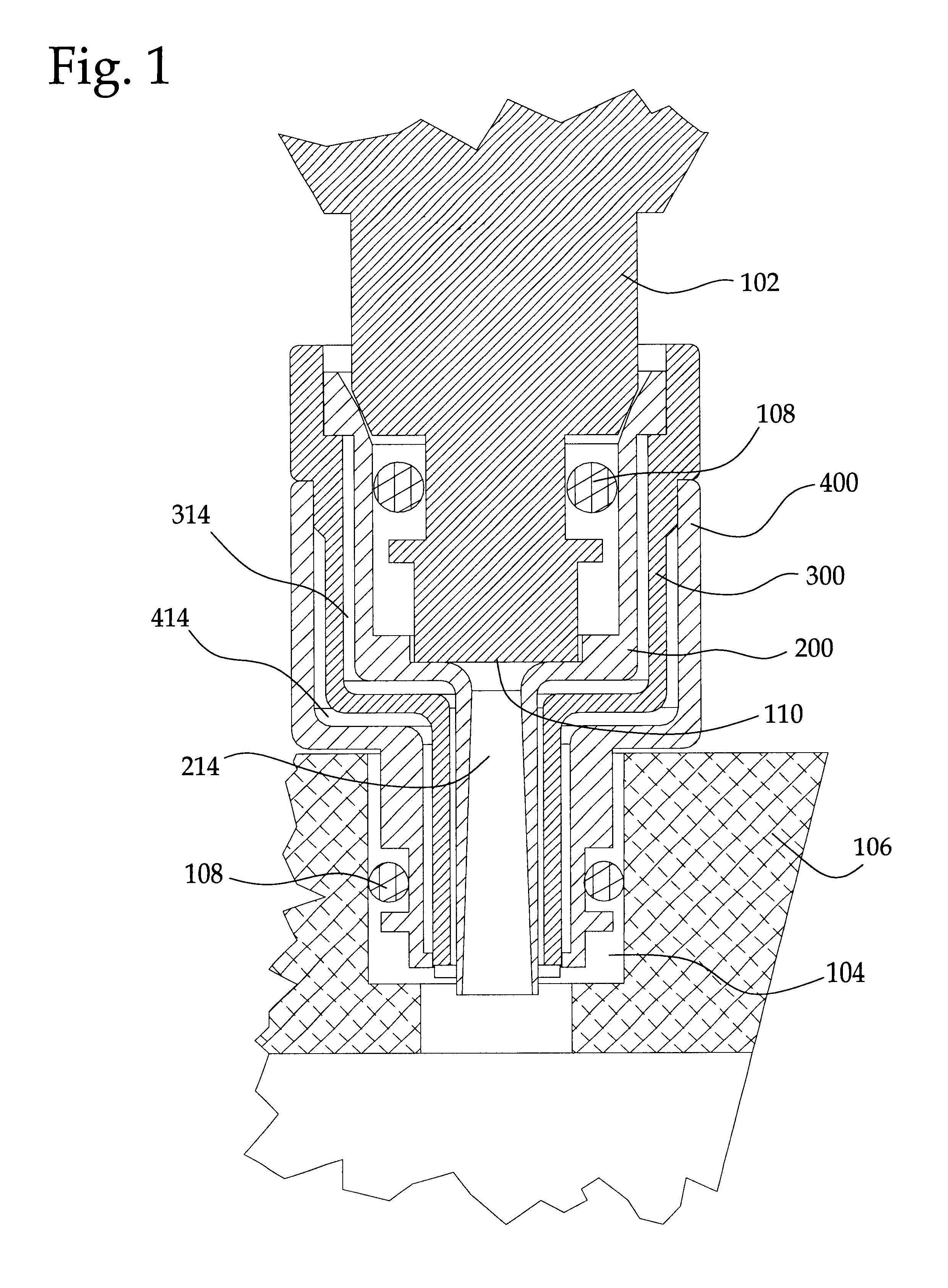
As used herein, the term “fuel injector” and “injector” refer to any type of fuel injector for supplying fuel into an internal combustion engine. For example, an injector may be of the type referred to as a “top feed” injector ...


PUM


Abstract

A fuel injector adapter for providing nitrous oxide to an internal combustion engine is disclosed. The nozzle has a fuel injector passage, having a central axis and terminating at an injector outlet, for passing fuel from a fuel injector to an engine. The nozzle also has one or more first auxiliary passages, which may be arranged in an annular pattern around the fuel injector passage, and which terminate at first outlets. The nozzle furthermore may have one or more second auxiliary passages, which also may be arranged in an annular pattern around the fuel injector passage, and which terminate at second outlets. The first auxiliary passages and second auxiliary passages are adapted to supply nitrous oxide or other additional combustion reactants to the engine. The nozzle may be attached to an engine intake and may be adapted to fit between a fuel injector and an engine without substantial modification to the engine.

Description

FIELD OF THE INVENTIONThe present invention relates generally to internal combustion engine performance enhancers and fuel system modification. More specifically, the present invention relates to nitrous oxide systems and alternative fuel systems for use with multipoint fuel injected engines.BACKGROUND OF THE INVENTIONOver the years, internal combustion engines have evolved into more efficient and powerful machines. As part of this evolution, the structures, dynamics, and control systems of modern engines have become highly specialized at burning either gasoline or diesel fuel. Although this evolution has made engines more efficient and has often resulted in modest power increases, the resulting engine designs have proven to be difficult to modify for specialty purposes using conventional modification techniques and devices. There is a need to provide new modification devices and methods that may be used with modern engine designs. In particular, there is a need to provide new ways ...

Claims


Application Information

Patent Timeline
IPC IPC(8): F02M63/02F02M63/00F02M61/00F02M61/16F02M61/14F02M25/00F02M21/02F02M43/00F02M43/04F02M35/10
CPCF02M25/00F02M21/0278F02M35/10216F02M35/1036F02M35/10367F02M43/00F02M43/04F02M61/14F02M61/145F02M61/16F02M61/162F02M63/0225F02M21/0281F02M35/10026Y02T10/146Y02T10/32Y02T10/12Y02T10/30
Inventor BAASCH, OSWALDFLYNN, DOUGLAS JOSEPHRUCKER, LAURA BETHWILSON, SHANE
Owner HOLLEY PERFORMANCE PRODUCTS
Why Eureka
Try Eureka