
Porcelain oven rack

Inactive Publication Date: 2005-01-04
AMERICAN APPLICANCE PROD INC
View PDF7 Cites 10 Cited by
  • Summary
  • Abstract
  • Description
  • Claims
  • Application Information

AI Technical Summary

Benefits of technology

The present invention provides a coated steel wire oven rack designed to be received within an oven cavity. The coated steel wire oven rack includes a plurality of elongated steel wire members joined together to form an oven rack having an outer surface; wherein the cross-sectional area of the steel rod material is reduced by at least about 20% when the steel rod material is drawn to form the steel wire; the outer surface of the oven rack being coated by a glass material, the glass material preferably being porcelain, wherein the amount of carbon in the steel rod material, the amount of carbon stabilizing transition metal in the steel rod material and the degree to which the cross-sectional area of the steel rod material is reduced, when the steel wire is drawn from the steel rod material is balanced so as to prevent chipping of the glass material away from the outer surface due to the release of hydrogen gas from the steel wire members when the steel wire is either heated or cooled.
The plurality of elongated steel wire members are made from steel rod material containing from about 80 to about 99.9% by weight of iron, from about 0.001 to about 0.08% by weight of carbon and from about 0.001 to about 0.2% by weight of a transition metal which will have a stabilizing effect on the carbon in the elongated steel wire members such that the carbon absorbs less hydrogen gas when the steel wire member is heated to temperatures above 500° F. than it would in the absence of the carbon stabilizing transition metal. In preferred embodiments, the transition metal is selected from the group consisting of Vanadium, Tantalum, Titanium and Niobium, and in the most preferred embodiment, the transition metal is Vanadium. The plurality of elongated steel wire members are preferably made from steel rod material by a process of area reduction. In the preferred process, the steel rod is pulled through a cold die that gradually reduces in diameter so that the rod is drawn repeatedly through the die and the cross-sectional area of the rod is reduced to form a steel wire having a cross-sectional area of diminished diameter. In preferred embodiments, the diameter of the steel wire is diminished at least about 20%, preferably at least about 30%, more preferably at least about 40%, even more preferably at least about 45%, and most preferably at least about 50%. It will be appreciated that the area reduction creates voids in the steel wire which are desirable to provide cavities into which hydrogen gas can release and, perhaps, compress, without creating pressure to be released from the surface of the steel wire once the steel wire is coated with porcelain. It will be appreciated, that the area reduction, which creates cavities in the steel wire, and the inclusion of carbon stabilizing transition metal elements which reduce the degree to which the carbon in the steel absorbs hydrogen, will diminish the degree to which hydrogen gas out-gassing causes cracking and chipping of the porcelain surface of the elongated steel wire members of the oven rack which are coated by the glass material.

Problems solved by technology

Such steel wire oven racks, however, are generally discolored when they are subjected to the high temperatures above 900 degrees F. associated with self-cleaning oven cycles which are common in today's kitchen ovens.

Method used


Image

  • Porcelain oven rack
  • Porcelain oven rack
  • Porcelain oven rack

Examples


Embodiment Construction

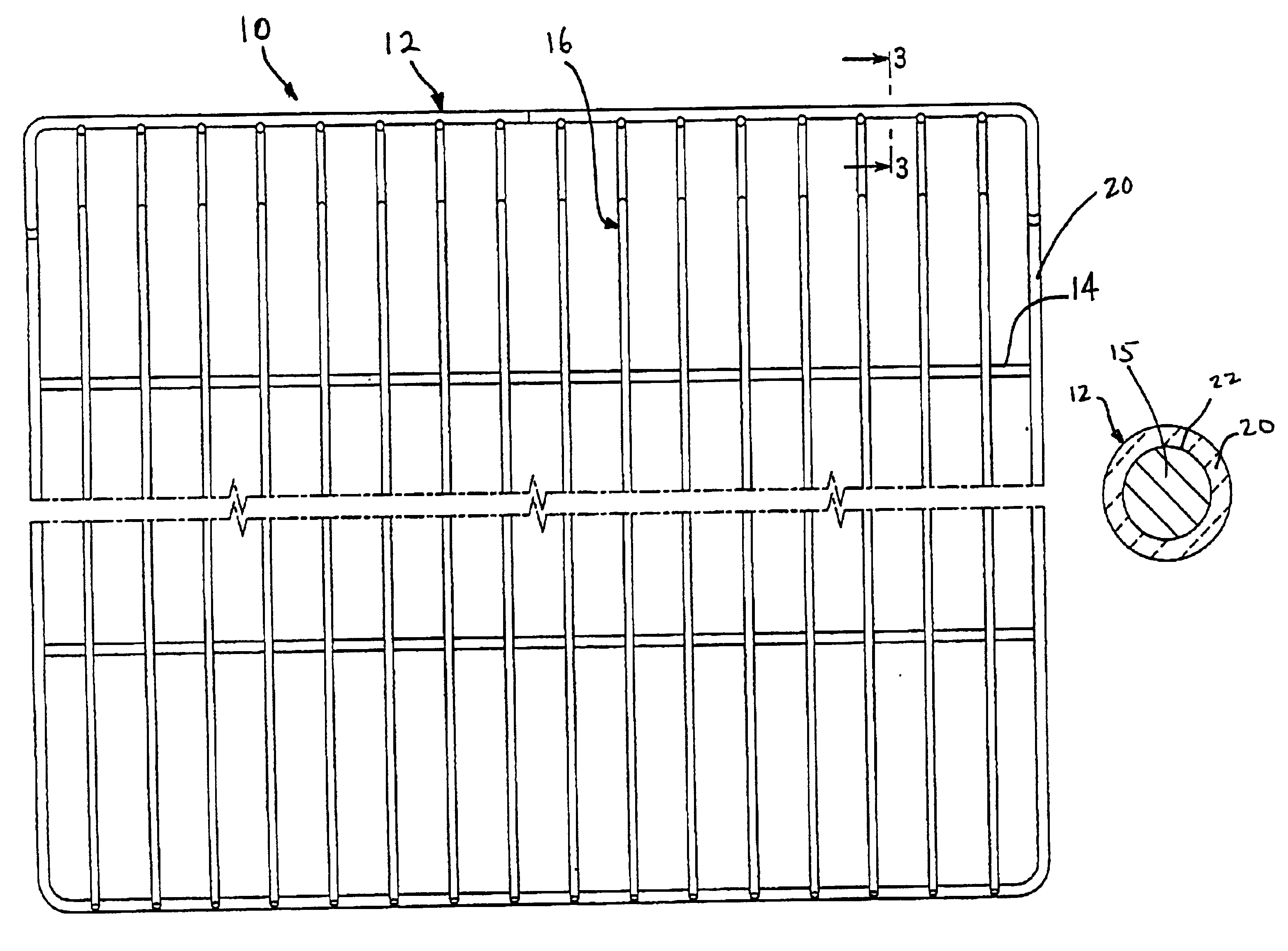
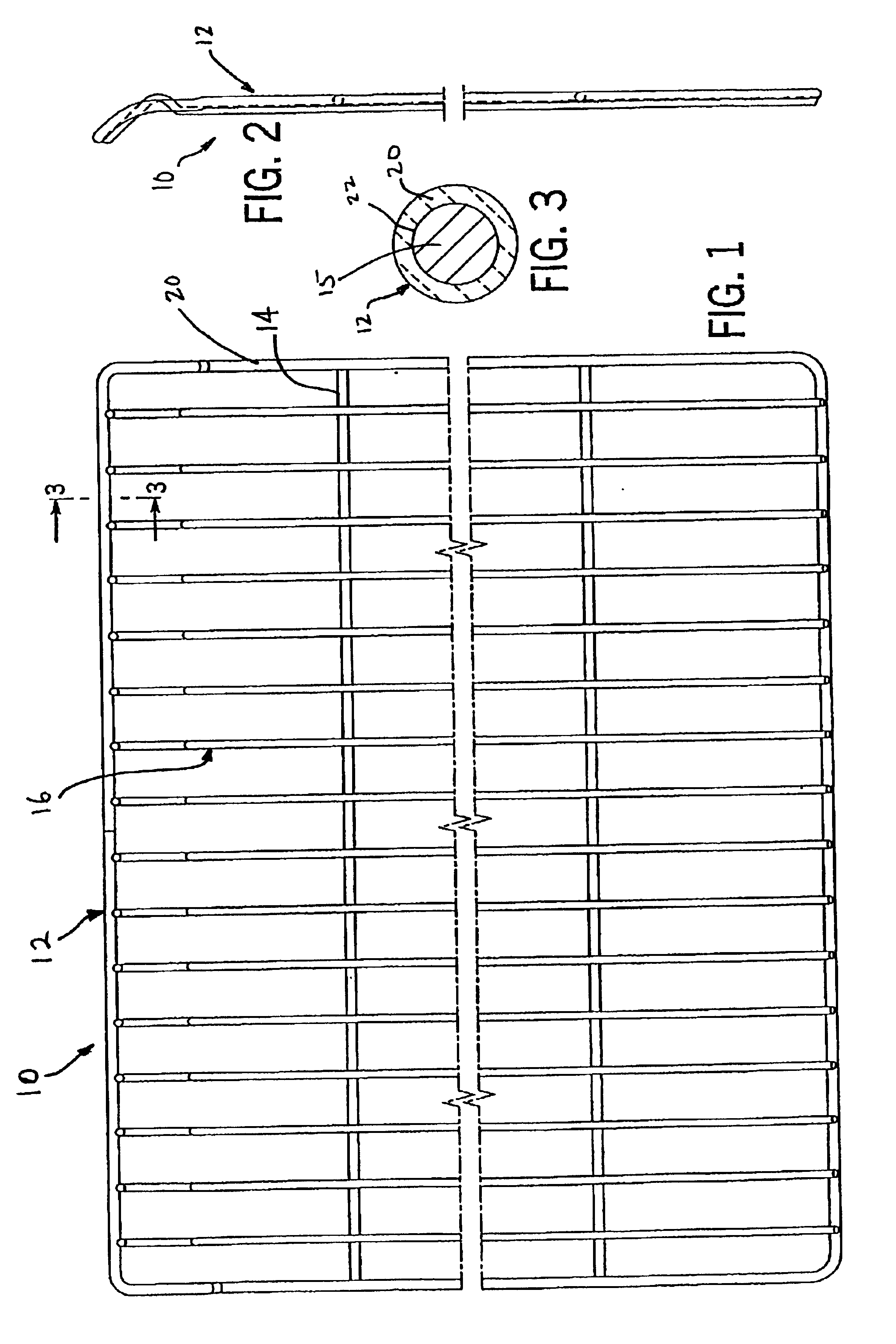
Referring now to the drawings, and in particular FIGS. 1-3, a coated steel wire oven rack 10 is shown. The coated steel oven wire rack 10 has an outside framing wire 12 stabilized by two frame stabilizing support wires 14 and a series of upper surface steel wire members 16 which generally run front to back to provide a support surface for oven utensils (not shown) that are placed on the coated oven rack 10.

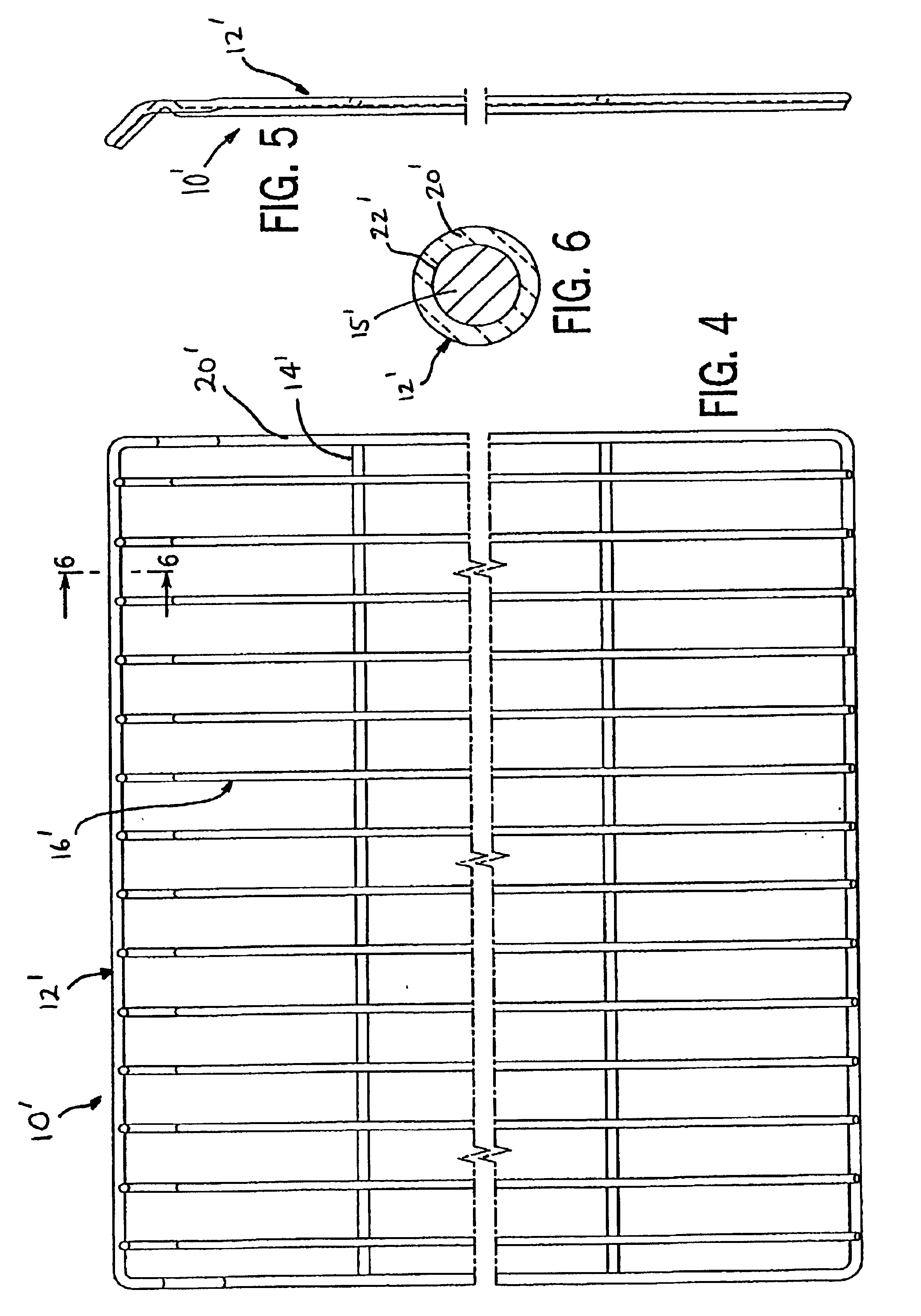
Referring now also to FIGS. 4-6, an alternate oven rack 10′ in accord with the present invention is shown that has only minor differences from the oven rack shown in FIGS. 1-3.

Referring now also to FIGS. 7-9, a further alternate oven rack 10″ in accord with the present invention is shown, having a few other minor differences, but in most other ways being virtually the same as the oven racks shown in FIGS. 1-6.

The present oven rack 10 is coated with a glass material 20, preferably porcelain, which is coated onto the outer surface 22 of welded steel wire parts 15 of the coated oven ...


PUM

PropertyMeasurementUnit
Temperatureaaaaaaaaaa
Fractionaaaaaaaaaa
Fractionaaaaaaaaaa

Abstract

In one embodiment, the present invention provides a coated steel wire oven rack. The preferred coated steel wire oven rack includes a plurality of elongated steel wire members joined together to form an oven rack having an outer surface. The plurality of elongated steel wire members are made from a steel rod material containing from about 80 to about 99.9% by weight of iron, from about 0.001 to about 0.08% by weight of carbon and from about 0.001 to about 0.2% by weight of a carbon stabilizing transition metal, preferably selected from the group consisting of Vanadium, Tantalum, Titanium and Niobium. The plurality of elongated steel wire members are preferably made from the steel rod material by drawing the steel rod material to form steel wire; wherein the diameter of the cross-sectional area of the steel rod material is reduced by at least about 20% when the steel rod material is drawn to form the steel wire. The outer surface of the oven rack is coated by a glass material, preferably porcelain; wherein the amount of carbon in the steel rod material, the amount of carbon stabilizing transition metal in the steel rod material and the degree to which the diameter of the cross-sectional area of the steel rod material is reduced, when the steel wire is drawn from the steel rod material, is optimized so as to prevent chipping of the glass material from the outer surface due to the release of hydrogen gas from the steel wire members when the steel wire is either heated or cooled. In preferred embodiments, the glass material is coated onto the oven rack in two distinct coating steps. The present invention also includes a method of making a coated steel wire oven rack comprising the steps of providing steel rod material; drawing the steel rod material to form steel wire; forming a plurality of elongated steel wire members; joining the plurality of steel wire members to one another to form a steel wire oven rack; and coating the steel wire oven rack with a glass material, preferably porcelain.

Description

FIELD OF THE INVENTIONThe present invention relates to steel wire products coated with glass material to protect the steel wire products from discoloration and the like due to heating the steel wire products at high temperatures. These steel wire products are preferably oven racks coated with porcelain to provide suitable oven rack surfaces for cooking, which do not discolor during cooking, or during self-cleaning cycles when the oven racks remain in the oven and the temperatures generally exceed the normal cooking temperatures.BACKGROUND OF THE INVENTIONSteel wire oven racks made from steel rod drawn to form steel wire are well-known in the industry. Such steel wire oven racks, however, are generally discolored when they are subjected to the high temperatures above 900 degrees F. associated with self-cleaning oven cycles which are common in today's kitchen ovens. It will be appreciated that improvements to address this discoloration problem and to increase color flexibility will be...

Claims


Application Information

Patent Timeline
IPC IPC(8): C23D5/00C23C30/00C23C28/04F24C15/16
CPCC23C30/00C23D5/00F24C15/16Y10T428/2913Y10T29/49874Y10T29/4962Y10T29/49194Y10T29/49885Y10T428/2956Y10T29/49888
Inventor BLANKENSHIP, DAVID JAMES
Owner AMERICAN APPLICANCE PROD INC
Learn More