
Liquid drop discharge method and discharge device; electro optical device, method of manufacture thereof, and device for manufacture thereof; color filter method of manufacture thereof, and device for manufacturing thereof; and device for incorporating backing, method of manufacturing thereof, and device for manufacture thereof

a discharge method and liquid drop technology, applied in the direction of power drive mechanisms, instruments, printing, etc., can solve the problems of ink jet head coming, complicated process, high cost, etc., and achieve the effect of preventing noise, easy wired connectors, and increasing manufacturing efficiency

Inactive Publication Date: 2005-01-04
KATEEVA
View PDF2 Cites 36 Cited by
  • Summary
  • Abstract
  • Description
  • Claims
  • Application Information

AI Technical Summary

Benefits of technology

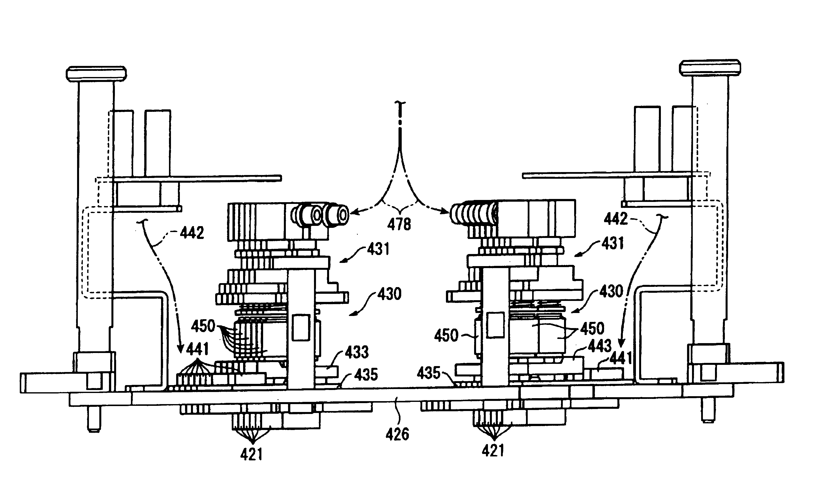
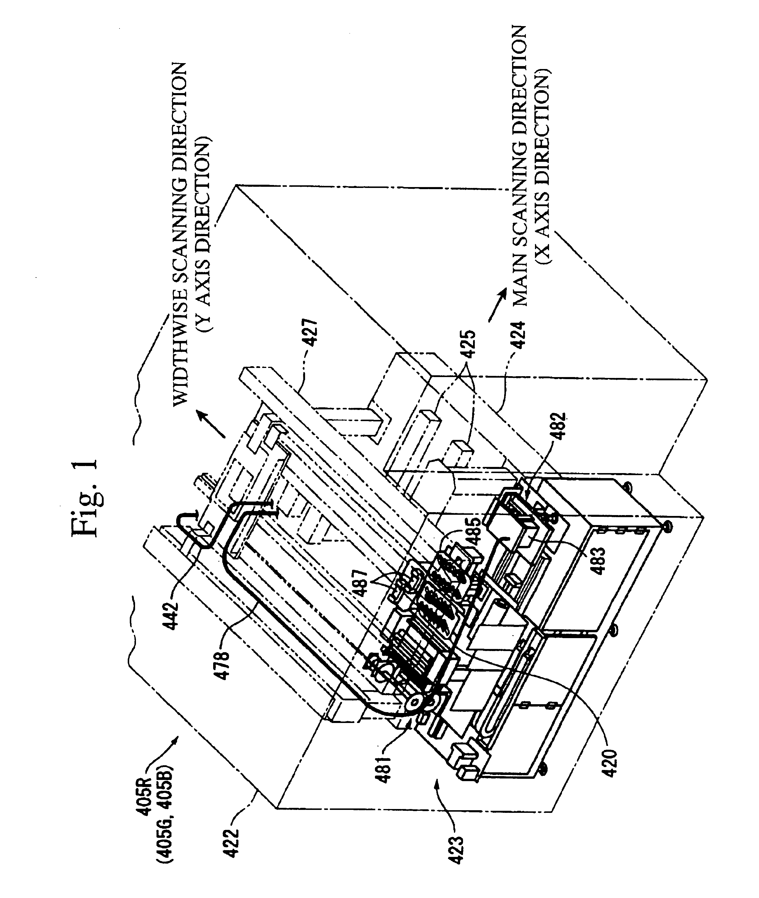
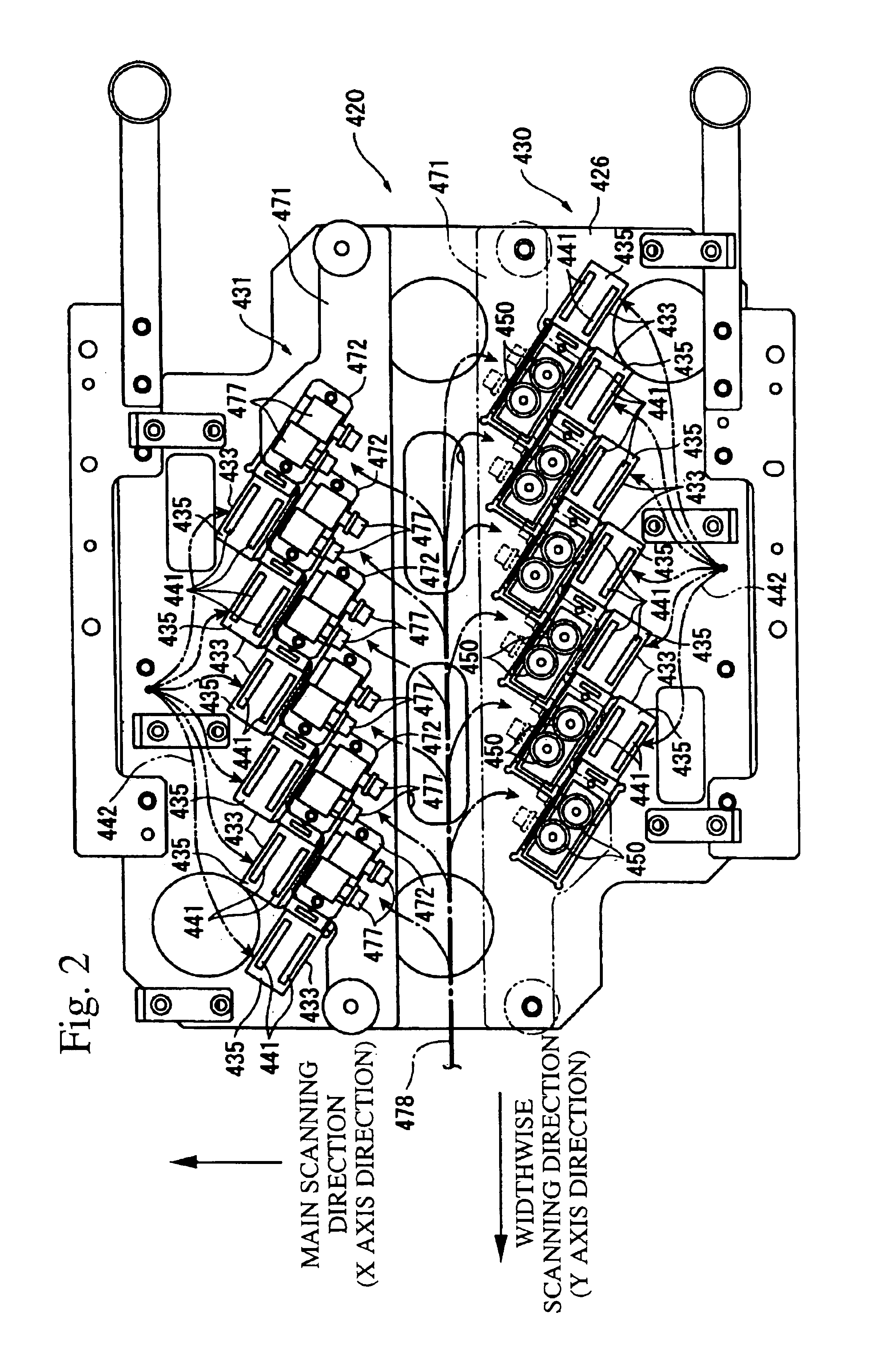
With the present invention having the above structure, because the plurality of discharge means, which comprise the liquid drop discharge heads and connectors on the mounting board, are arranged on holding means, it becomes to be easier to compose the discharge device, and the productivity of manufacturing the discharge device increases. Because the connectors of one the groups do not face the discharge means in the other of the groups, a portion of the mounting board of one of the groups on which the connectors are arranged is orientated to an outer side of the mounting board where opposes to the liquid drop discharge head of the other of the groups, and therefore an efficiency of wiring to the connectors increases. According to the discharge means thus wired, because a mutual influence among the electrical noise from the connectors is prevented, the discharge of the liquid mass is stabilized.
According to the present invention, the discharge means, comprising the liquid drop discharge heads and the connectors being arranged on the mounting board, are separated into the groups and mounting board is orientated so that the portion the on which the connectors of one of the groups are arranged does not face to the discharge means of the other of the groups, and the liquid drop discharge head is shifted relative to the object onto which liquid drops are to be discharged while a plane in which the nozzles are aligned lays along the surface of the object onto which liquid drops are to be discharged so as to discharge the liquid mass to the object onto which liquid drops are to be discharged, therefore, it is possible to construct the discharge means easier compared with respectively constructing the plurality of liquid drop discharge means with corresponding connectors and also possible to increase a manufacturing efficiency. And the mounting board is orientated so that the portion on which the connectors of one of the groups are arranged does not face to the discharge means of the other of the groups, and the portion on which the connectors are arranged is orientated so that the portion faces to the outer periphery of the mounting board which is opposite with the liquid drop discharge head, and therefore, it is possible to easily wire the connectors and also to increase a manufacturing efficiency. Further, by the connectors thus arranged in the discharge means it is possible to prevent a noise from one of the connectors which influences to the other of the connector and also possible to stably discharge the liquid mass.

Problems solved by technology

In the past, there has been a per se known method of using photolithography when patterning the filter elements of a color filter of various colors such as R, G, and B, or when patterning the picture elements of an electroluminescent device of various colors such as R, G, and B. However there are certain problems when using this photolithography method, such as the fact that the process is complicated, the fact that large quantities of the color material or the photoresist are consumed, the fact that the cost becomes high, and the like.
However there is the problem that, if a motherboard 301 is utilized whose size is different from and does not correspond to the size of the panel regions 302, every time this happens, a different ink jet head comes to be required, and accordingly the cost is increased.

Method used


Image

  • Liquid drop discharge method and discharge device; electro optical device, method of manufacture thereof, and device for manufacture thereof; color filter method of manufacture thereof, and device for manufacturing thereof; and device for incorporating backing, method of manufacturing thereof, and device for manufacture thereof
  • Liquid drop discharge method and discharge device; electro optical device, method of manufacture thereof, and device for manufacture thereof; color filter method of manufacture thereof, and device for manufacturing thereof; and device for incorporating backing, method of manufacturing thereof, and device for manufacture thereof
  • Liquid drop discharge method and discharge device; electro optical device, method of manufacture thereof, and device for manufacture thereof; color filter method of manufacture thereof, and device for manufacturing thereof; and device for incorporating backing, method of manufacturing thereof, and device for manufacture thereof

Examples


Embodiment Construction

A Preferred Embodiment Related to s Method of Manufacture of a Color Filter, and a Device for Manufacturing the Same

Next, a preferred embodiment of the device for manufacture of a color filter according to the present invention will be explained with reference to the figures. First, before explaining this device for manufacture of a color filter, the color filter which is to be manufactured will be explained. FIG. 12 is a figure which shows a portion of the color filter in a magnified view; its view 12(A) shows a plan view thereof, while the view 12(B) shows a sectional view thereof taken in a plane shown by the line X—X in FIG. 12(A). It should be understood that, with this color filter shown in FIG. 12, the portions for which the structure is the same as that of corresponding portions in the color filter of the preferred embodiment shown in FIG. 5 are designated by the same reference symbols.

Construction of the Color Filter

First, a preferred embodiment of a color filter manufactur...


PUM


Abstract

A liquid drop discharge device provides a head unit 420 which discharges filter element material relative to each of various colors of color filters. The head unit 420 is composed of an ink jet heads which are arranged on one end of a print substrate plate having a shape of rectangular card and head devices 433 which are arranged on the other end of the print substrate plate comprising connectors 441. The head devices 433 are aligned in two rows, as two groups, in a staggered arrangement so that a portion on which the connectors 441 are aligned in one of the two rows does not face to the same portion of the other in the two rows and protrudes outside of the print substrate plate. The head unit 420 discharges the filter element material onto predetermined portions in a superimposing manner while shifting along a direction which intersects to a direction along which the head devices 433 are arranged.

Description

FIELD OF THE INVENTIONThe present invention relates to a discharge method and device for discharging a liquid mass which has a certain flowability.And, the present invention relates to an electro optical device such as a liquid crystal device, an electroluminescent device, an electrical migration device, an electron emission device or a PDP (Plasma Display Panel) device or the like, to a method of manufacture of an electro optical device for manufacturing such an electro optical device, and to a device for manufacturing the same. Furthermore, the present invention relates to a color filter which is used in an electro optical device, and to a method of manufacture of such a color filter and to a device for manufacturing the same. Yet further, the present invention relates to a device which comprises a backing such as an electro optical member, a semiconductor device, an optical member, a reagent inspection member or the like, and to a method of manufacture of such a device which comp...

Claims


Application Information

Patent Timeline
Patent Type & Authority Patents(United States)
IPC IPC(8): B41J2/15B41J2/14B41J2/145B41J25/00
CPCB41J2/14B41J2/15G02F1/133516G02F1/1303B41J2202/09H01L51/56G02F1/1362H01L51/0005H10K71/135H10K71/40H10K71/191B41J25/00H10K71/00
Inventor NAKAMURA, SHINICHI
Owner KATEEVA
Learn More