
Pressure feed coating application system

a technology of coating application system and pressure feed, which is applied in the direction of superimposed coating process, liquid/solution decomposition chemical coating, manufacturing tools, etc., can solve the problems of product defects, safety hazards, product defects, etc., and achieve rapid change of coatings, increased control, and wide film thickness control range

Inactive Publication Date: 2005-01-04
PANKAKE EUGENE A
View PDF37 Cites 0 Cited by
  • Summary
  • Abstract
  • Description
  • Claims
  • Application Information

AI Technical Summary

Benefits of technology

The present invention includes a device for and a method of-applying a coating to a material web such as, but not restricted to, a sheet of steel, aluminum, textile, paper, or film. An elongated feed nozzle is used to feed coating material under pressure. The pressure may be supplied by gravity or by a low pressure pump. The feed nozzle seals-up against either the web or a roll. The feed nozzle includes a fluid reservoir, a metering surface, end seals (end closures) and a back seal. The fluid reservoir, in conjunction with the end seals and the back seal, forms a cavity which contains the fluid as it is being fed through the feed nozzle. This avoids all the problems of having the coating in open trays. The present invention further provides a mechanism for rotating one nozzle out of the operating position and another nozzle into operating position,permitting a very quick change of coatings. With this arrangement, the nozzle that is off-line can be cleaned and prepared while the on-line nozzle is operating. The present invention also provides a support spring, which supports the nozzle and provides automatic position adjustment of the nozzle in response to the amount of force being exerted by the nozzle. The preferred embodiment also provides a nozzle contact angle adjustment mechanism, a mechanism to adjust the profile of the metering surface, a feed nozzle force sensor, a feed nozzle cleaning assembly, and an applicator roll cleaning assembly. A stiffener is used to make the metering surface rigid. The stiffener can be integral with the feed nozzle, or a separate stiffener can be attached to the feed nozzle. A preferred embodiment permits feed nozzle force control and contact surface angle control to be operated independently of one another, which cannot be achieved with die or slot coating. These technologies require precise control of clearances. The support spring, as the frame deflects and polymer covered rolls deform, permits the rotation of the feed nozzle to maintain a proper geometry, permitting increased control and a wider film thickness control range for a specific nozzle shape. The additional dynamic actuators of nozzle force and metering surface add new quality, speed and film thickness capability to web coating. Dynamic feed nozzle force control can be accomplished independent of reservoir cavity pressure and metering surface contact angle.

Problems solved by technology

This process is normally limited to speeds up to approximately 200 feet per minute.
Numerous other defects are also associated with unstable or uncontrolled fluid dynamics that occur at the entry point of the roll into the fluid contained in the pan, the exit point of the roll out of the fluid in the pan, or at the nip point.
The fluid picked up out of a pan is susceptible to being slung from the roll ends, creating a safety hazard, product defects, and a mess.
The appearance and thickness of the applied fluid is governed by a very complex relationship between the equipment configuration, equipment settings, and the fluid characteristics.
The evaporation of these large volumes of solvents into the atmosphere is very undesirable from an environmental standpoint.
Also, since the solvents evaporate from the open pan during the process, the characteristics of the coating are constantly changing during the process, making it very difficult to control the process.
The use of open pans also creates major limitations to rapid, repeatable product changes.
To achieve product changes in less than 30 minutes usually requires additional investments of millions of dollars in capital equipment and labor intensive activities on major web processing lines.

Method used


Image

  • Pressure feed coating application system
  • Pressure feed coating application system
  • Pressure feed coating application system

Examples


Embodiment Construction

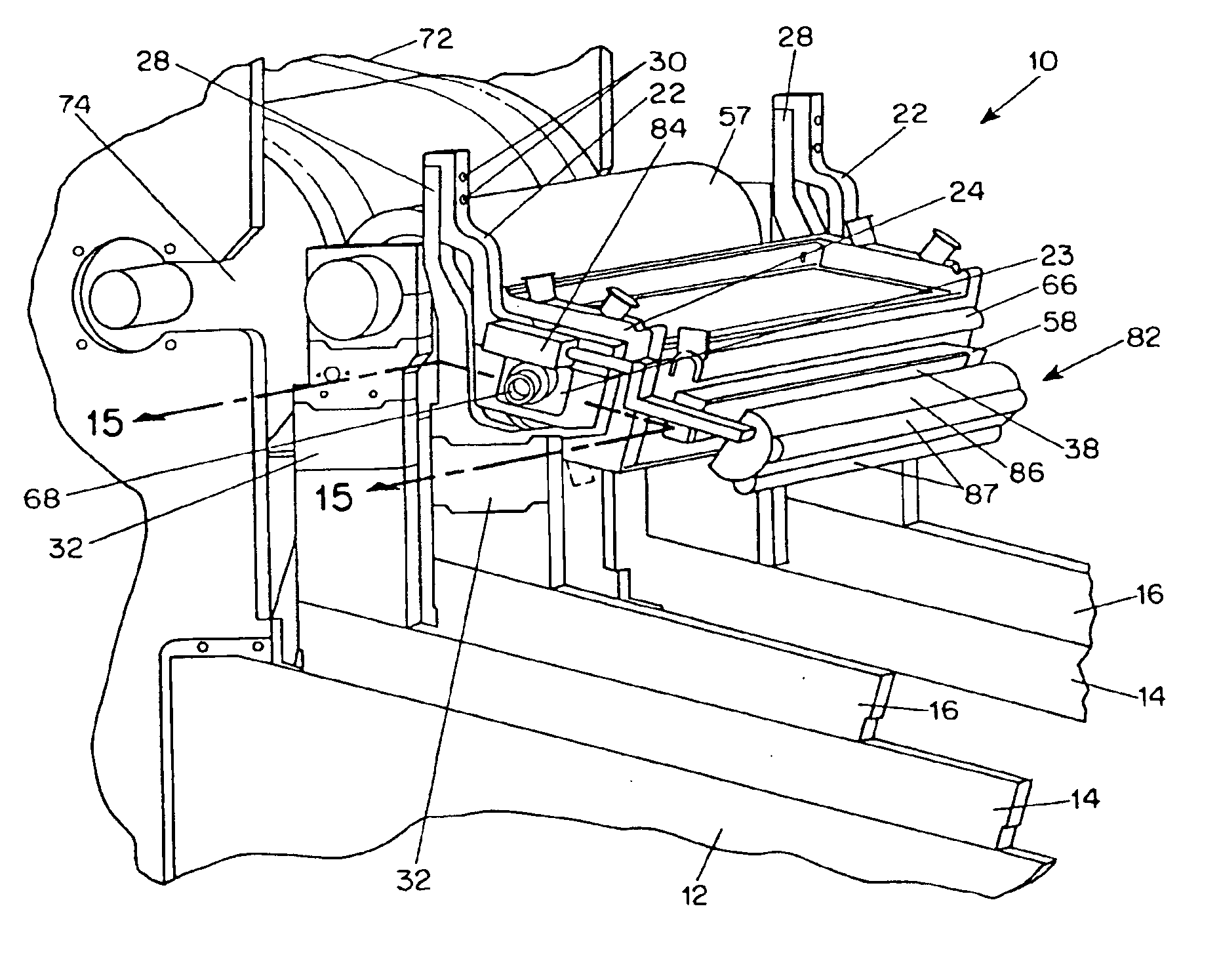
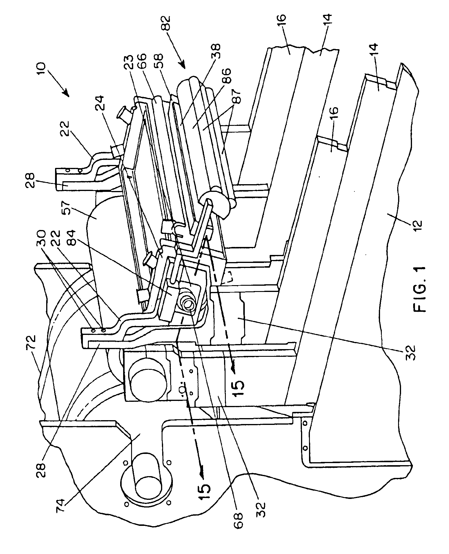
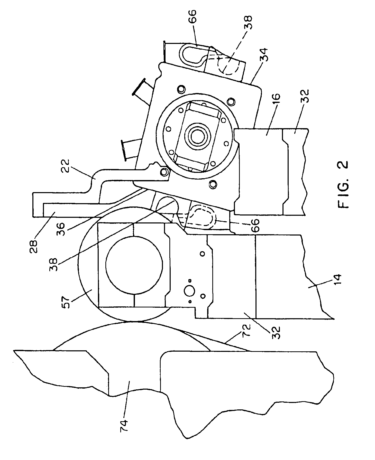
FIGS. 1-16 show a first preferred embodiment of a system 10 for coating a web of material made in accordance with the present invention. (FIGS. 10A-10C show an alternate embodiment using a different type of seal.) The system 10 includes a stationary base 12, and left and right movable roller support and nozzle support frames 14, 16 mounted on the base 12. The left and right sides of this system 10 are essentially mirror images of each other. Each of the movable frames 14, 16 is mounted on a linear bearing arrangement 18, as shown in FIGS. 6-8, and the position of each movable frame member 14, 16 is controlled by a stepper motor, as will be explained in more detail later. Left and right springs 22 are mounted on the left and right nozzle support frames 16. Mounting blocks 23 are bolted to their respective springs 22. In this preferred embodiment, the springs 22 are leaf springs, although other types of springs could be used. One end of each spring 22 is bolted onto an upwardly-projec...


PUM

PropertyMeasurementUnit
Angleaaaaaaaaaa
Angleaaaaaaaaaa
Lengthaaaaaaaaaa

Abstract

The present invention includes a device and a method of applying a coating to a web. The preferred device comprises a feed nozzle coupled to a stiffener coupled to a spring coupled to a position / force adjuster. The feed nozzle comprises a fluid reservoir, a feed pipe, a metering surface, end seals and a back seal. The stiffener spring, as the frame deflects and polymer covered rolls deform, permits the rotation of the feed nozzle so a proper geometry is maintained, permitting increased control and a wider film thickness control range for a specific nozzle shape. This device permits greater film thickness control, ability to process at much higher speeds than currently achievable, and a wider range of film thickness. This device permits coatings to be applied at much wider ranges of rheological characteristics. Coatings can be applied at higher percent solids with improved characteristics. Multiple feed nozzles provide rapid product changeover for greater equipment utilization and higher productivity.

Description

BACKGROUNDThe present invention relates to systems for applying coatings under pressure to a web of material. A variety of coatings may be used, such as, but not restricted to, solvent- or water-based coatings, and the web may be made of a variety of materials, such as, but not restricted to, steel, aluminum, textiles, paper or film. U.S. Pat. No. 5,743,964 “Pankake” is an example of prior art roll coating.The primary known technology for application of film in the range of 1 milligram per square inch to 30+milligrams per square inch of fluid on a substrate at speeds greater than 250 feet per minute involves a process known as roll coating. This involves picking up a fluid out of an open pan with a pick-up roll or feeding the fluid by gravity into a top nip. (A nip is the pinch point between rollers.) The fluid is then transferred from that roll to the next or is transmitted through a nip to the next roll. Eventually, the fluid is transferred from a roll to the web.Another approach ...

Claims


Application Information

Patent Timeline
IPC IPC(8): B05C3/18B05C1/08B05C3/00B05C9/00B05C3/02B05C3/12B05C9/04B05C5/02B05C11/04
CPCB05C1/0813B05C1/0839B05C3/18B05C1/0873B05C9/04B05C3/125B05D1/28
Inventor PANKAKE, EUGENE A.
Owner PANKAKE EUGENE A
Learn More