Power amplifier capable of adjusting operating point

a technology of power amplifier and operating point, which is applied in the direction of amplifier, amplifier with semiconductor device/discharge tube, amplifier, etc., can solve problems such as deterioration of evm, and achieve the effect of high degree of accuracy

Inactive Publication Date: 2005-01-04
ALPS ALPINE CO LTD
View PDF8 Cites 30 Cited by
  • Summary
  • Abstract
  • Description
  • Claims
  • Application Information

AI Technical Summary

Benefits of technology

In view of such circumstances, an object of the present invention is to provide a power amplifier that is capable of adjusting the operating point, in which the output of the bias control circuit for supplying a bias voltage to the power amplifying stage is varied in phase to achieve reduction of power consumption and improvement of the linear performance.
According to the aforementioned unit, the power amplifying element is adapted to be switched between the amplifying action and the non-amplifying action by supplying a switching voltage to the bias control circuit to eliminate power consumption by the power amplifying element in non-amplifying action, and a supplied bias voltage value may be selected by supplying an operating point adjusting voltage having phased bias voltage values to the bias control circuit. Therefore, the power amplifying element can be set to an operating point suitable to that moment, and thus power consumption of the power amplifying stage can be maintained constantly at the value lower than the limit value, as well as the output signal can be controlled so as to satisfy the linear performance standard.
In this arrangement, the power amplifying element can be set to either one of the operating points suitable to that moment with a relatively simple unit, whereby power consumption of the power amplifying stage can be constantly maintained at a value below the limit value, and the output signal can be controlled to a value satisfying the linear performance standard.
In this arrangement, the power amplifying element can be set to one of the operating point suitable to that moment with high degree of accuracy, whereby power consumption of the power amplifying stage can be constantly maintained at the value below the limit value, and the output signal can be controlled to a value satisfying the linear performance standard.

Problems solved by technology

Generally, the fact that the linear performance of the wireless transmitting signal is determined mainly by the characteristics of the transmitting signal output amplifier (power amplifier) is known, and the fact that unnecessary signal components such as AM-AM conversion components or AM-PM conversion components are generated in the power amplifier when the linear performance of the power amplifier is not satisfactory, and such unnecessary signal components may cause deterioration of EVM is also known.

Method used


Image

  • Power amplifier capable of adjusting operating point
  • Power amplifier capable of adjusting operating point
  • Power amplifier capable of adjusting operating point

Examples


first embodiment

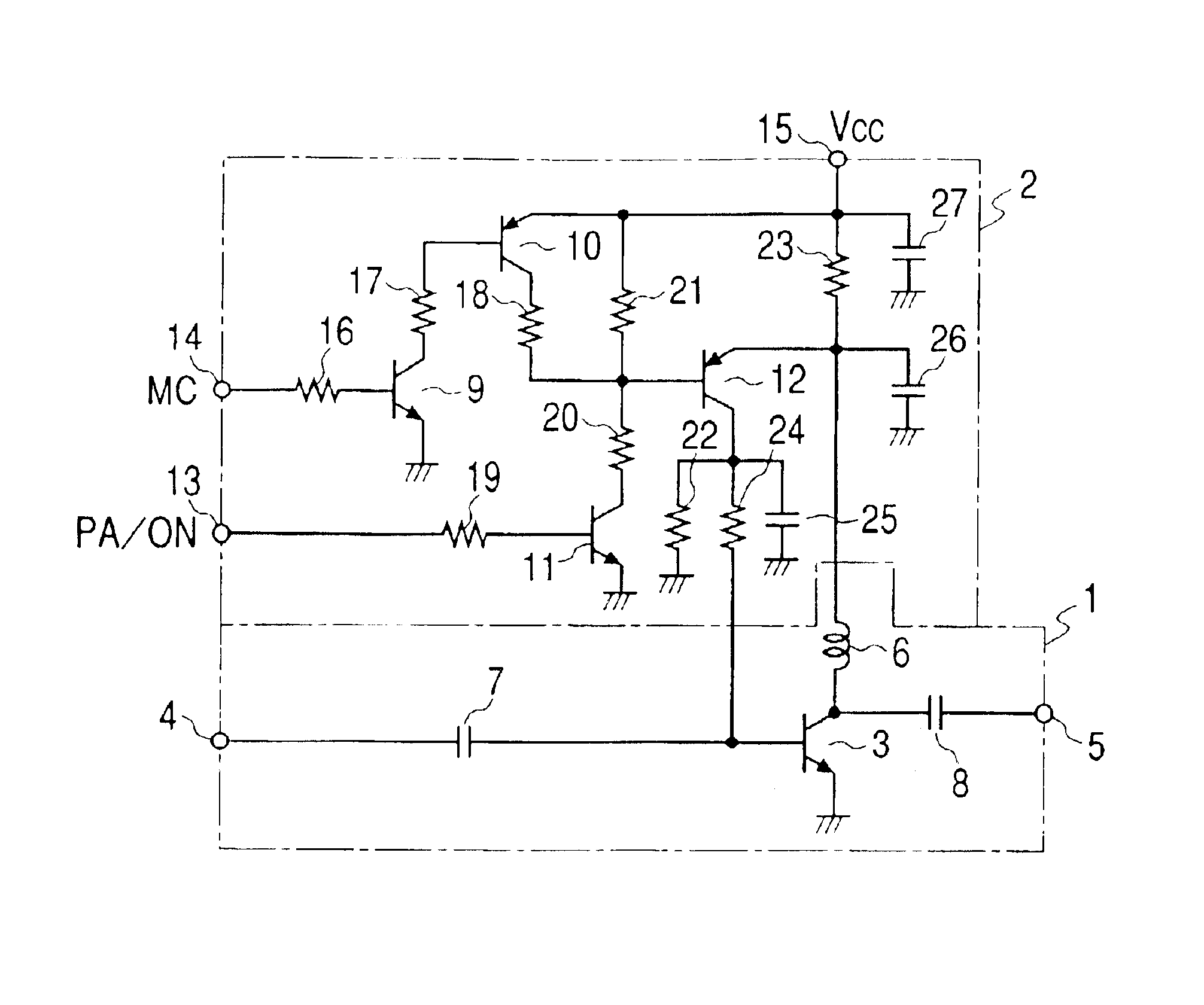
FIG. 1 is a circuit diagram according to a power amplifier that is capable of adjusting the operating point according to the present invention, showing a construction of principal portion in which a power amplifying stage is constructed of independent elements.

As shown in FIG. 1, the power amplifier according to the first embodiment includes a power amplifying stage 1 and a bias control circuit 2. In this case, the power amplifying stage 1 includes a power amplifying transistor 3, a radio-frequency signal input terminal 4, a radio-frequency signal output terminal 5, a load inductor 6, a first coupling capacitor 7, and a second coupling capacitor 8. The bias control circuit 2 includes a first control transistor 9, a second control transistor 10, a third control transistor 11, a fourth control transistor 12, a bias switching voltage (PA / ON) input terminal 13, a mode control voltage (MC) input terminal 14, a power source terminal 15, a first resistance 16, a second resistance 17, a thi...

second embodiment

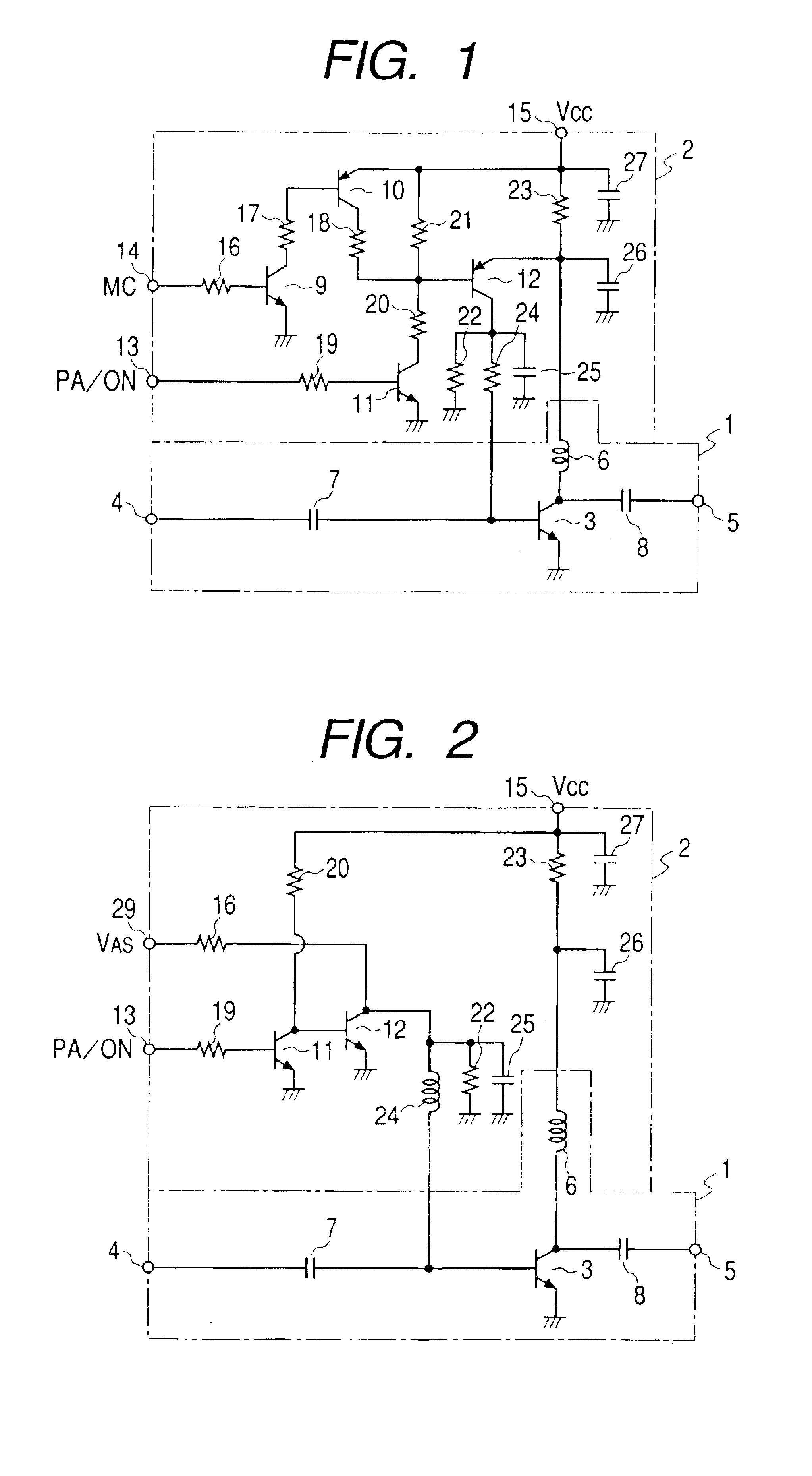
FIG. 2 is a power amplifier that is capable of adjusting an operating point according to the present invention, showing a construction of a principal portion in which a power amplifying stage is constructed of independent elements.

In FIG. 2, the same components as those shown in FIG. 1 are designated by the same reference numerals. In the description described below, the power amplifier according to the first embodiment is referred to as a first embodiment, and the power amplifier according to the second embodiment is referred to as a second embodiment.

As shown in FIG. 2, the second embodiment includes a power amplifying stage 1 and a bias control unit 2. The construction of the power amplifying stage 1 is the same as the construction of the power amplifying stage 1 of the first embodiment. The bias control circuits 2 differ in construction in that the first embodiment employs a binary mode control voltage (MC) including a low level (L) and a high level (H) as an operating point adj...

third embodiment

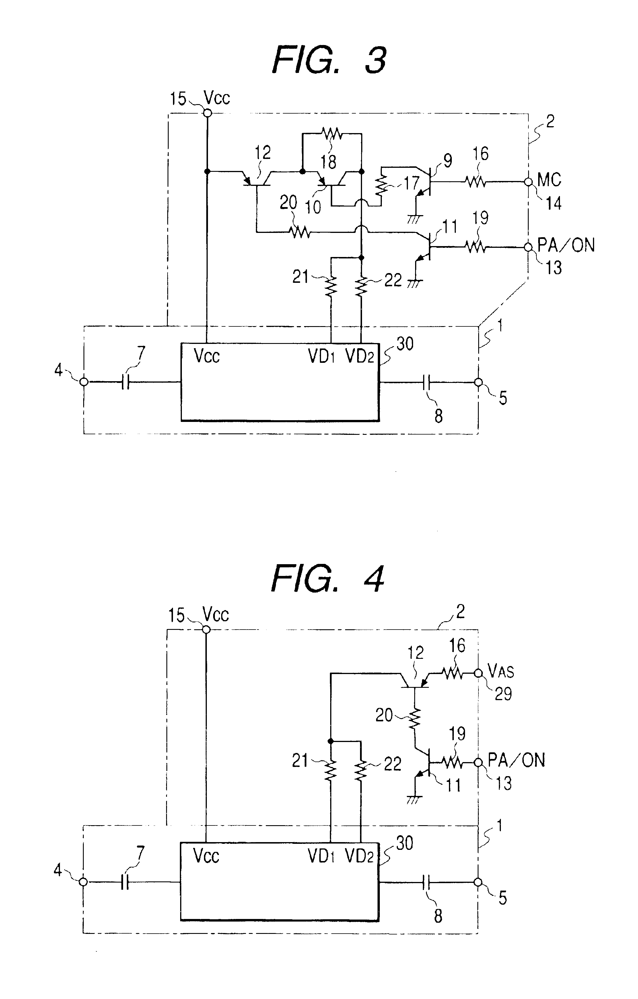
FIG. 3 is a power amplifier that is capable of adjusting an operating point according to the present invention, showing a construction of a principal portion in which a power amplifying stage is constructed of a Microwave Monolithic Integrated Circuit (MMIC).

As shown in FIG. 3, the power amplifier according to the third embodiment includes a power amplifying stage 1, and a bias control circuit 2. In this case, the power amplifying stage 1 includes an MMIC 30, a radio-frequency signal input terminal 4, a radio-frequency signal output terminal 5, a first coupling capacitor 7, and a second coupling capacitor 8. The bias control circuit 2 includes a first control transistor 9, a second control transistor 10, a third control transistor 11, a fourth control transistor 12, a bias switching voltage (PA / ON) input terminal 13, a mode control voltage (MC) input terminal 14, a power source terminal 15, a first resistance 16, a second resistance 17, a third resistance 18, a fourth resistance 19,...


PUM


Abstract

The present invention includes a power amplifying stage having a power amplifying element having a main electrode and a control electrode, and a bias control circuit that is supplied with a bias switching voltage and an operating point adjusting voltage for adjusting the bias voltage value to the control electrode of the power amplifying element by the bias switching voltage and the operating point adjusting voltage and hence adjusting the operating point of the power amplifying element, wherein the bias control circuit adjusts the operating point of the power amplifying element by switching between supply and stop of the bias voltage to the control electrode of the power amplifying element by the bias switching voltage, and varying the bias voltage value to be supplied to the control electrode of the power amplifying element by the operating point adjusting voltage in phase.

Description

BACKGROUND OF THE INVENTION1. Field of the InventionThe present invention relates to a power amplifier that is capable of adjusting an operating point and, more specifically, to a power amplifier that is capable of adjusting an operating point, in which bias voltage to be supplied to a control electrode of a power amplifying element that constitutes the power amplifier is varied in phase and adjusting gain of the power amplifier corresponding to variations in bias voltage.2. Description of the Related ArtIn the related art, in a Wireless LAN, standardized specifications for wireless transmitting / receiving signals are established by IEEE (Institute of Electrical and Electronics Engineers). In this case, in one of the standardized specifications, IEEE802.11a, specifies that the type of the wireless transmitting / receiving signal is OFDM (Orthogonal Frequency Division Multiplexing) system, and a system in which a primary modulation varies from BPSK (Binary Phase Shift Keying) of 6 Mbps ...

Claims


Application Information

Patent Timeline
Patent Type & Authority Patents(United States)
IPC IPC(8): H03F1/30H03F1/02H03F1/32H03F3/213H03G3/10
CPCH03F1/302
Inventor IZUMIYAMA, TORUTAKESHITA, HIDEKI
Owner ALPS ALPINE CO LTD
Why Eureka
Try Eureka