Method of activating optical communication system, channel increasing/decreasing method, and computer-readable recording medium

a technology of optical communication system and activation method, applied in the direction of electromagnetic repeaters, transmission monitoring, instruments, etc., can solve the problem of determining and adjusting separately

Inactive Publication Date: 2005-01-04
FUJITSU LTD
View PDF26 Cites 173 Cited by
  • Summary
  • Abstract
  • Description
  • Claims
  • Application Information

AI Technical Summary

Benefits of technology

According to the present invention, slope compensation, peak power control, and pre-emphasis can be optimally reliably performed in the optical communication system.
According to the channel increasing / decreasing method described above, slope compensation, peak power control, and pre-emphasis can be optimally reliably performed in the optical communication system even after the channel is increased or decreased.

Problems solved by technology

Since these amounts depend on one another, the optical communication system which adjusts all the amounts cannot separately determine and adjust them.

Method used


Image

  • Method of activating optical communication system, channel increasing/decreasing method, and computer-readable recording medium
  • Method of activating optical communication system, channel increasing/decreasing method, and computer-readable recording medium
  • Method of activating optical communication system, channel increasing/decreasing method, and computer-readable recording medium

Examples


first embodiment

[Operation and Effects of First Embodiment]

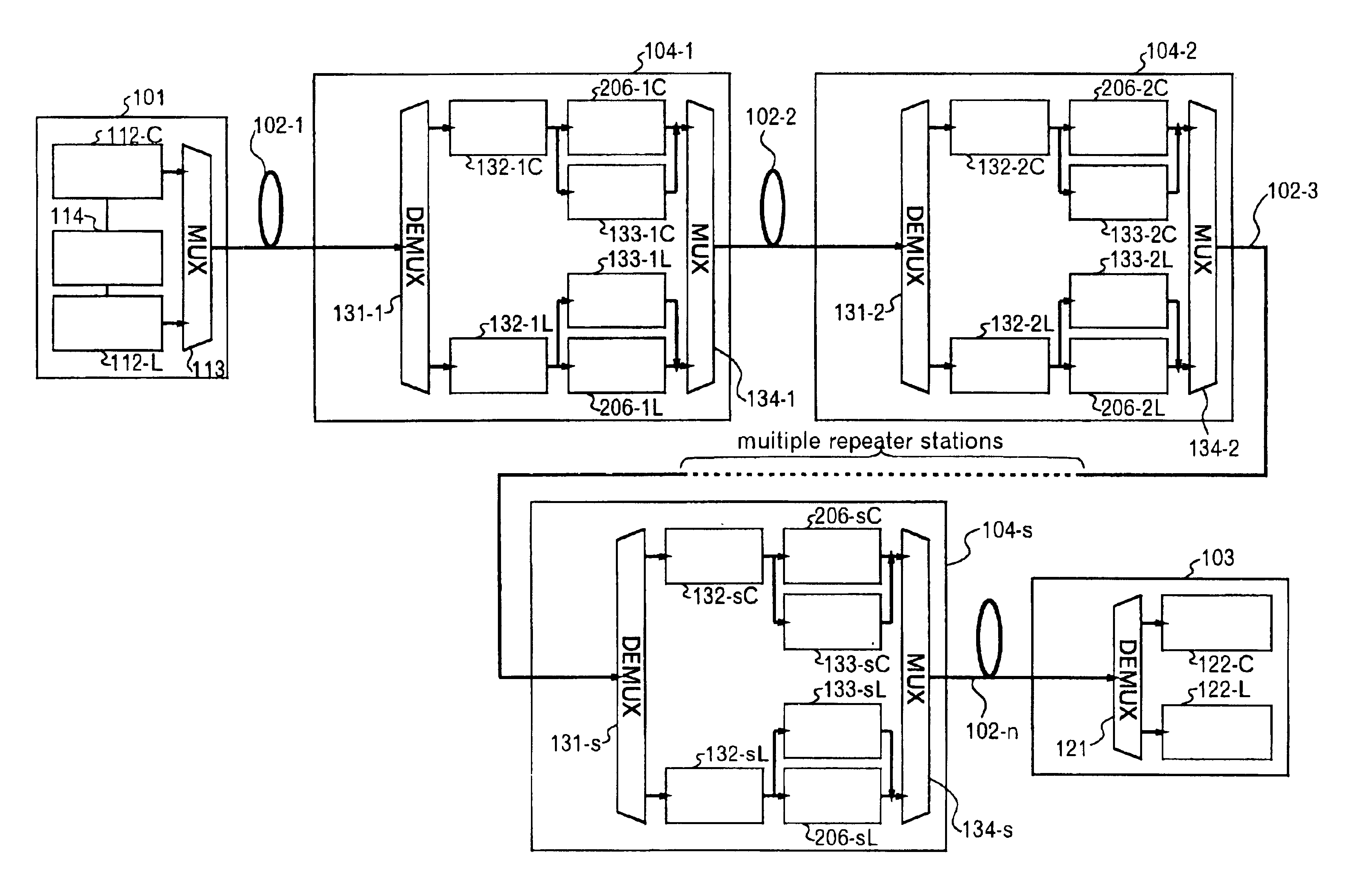
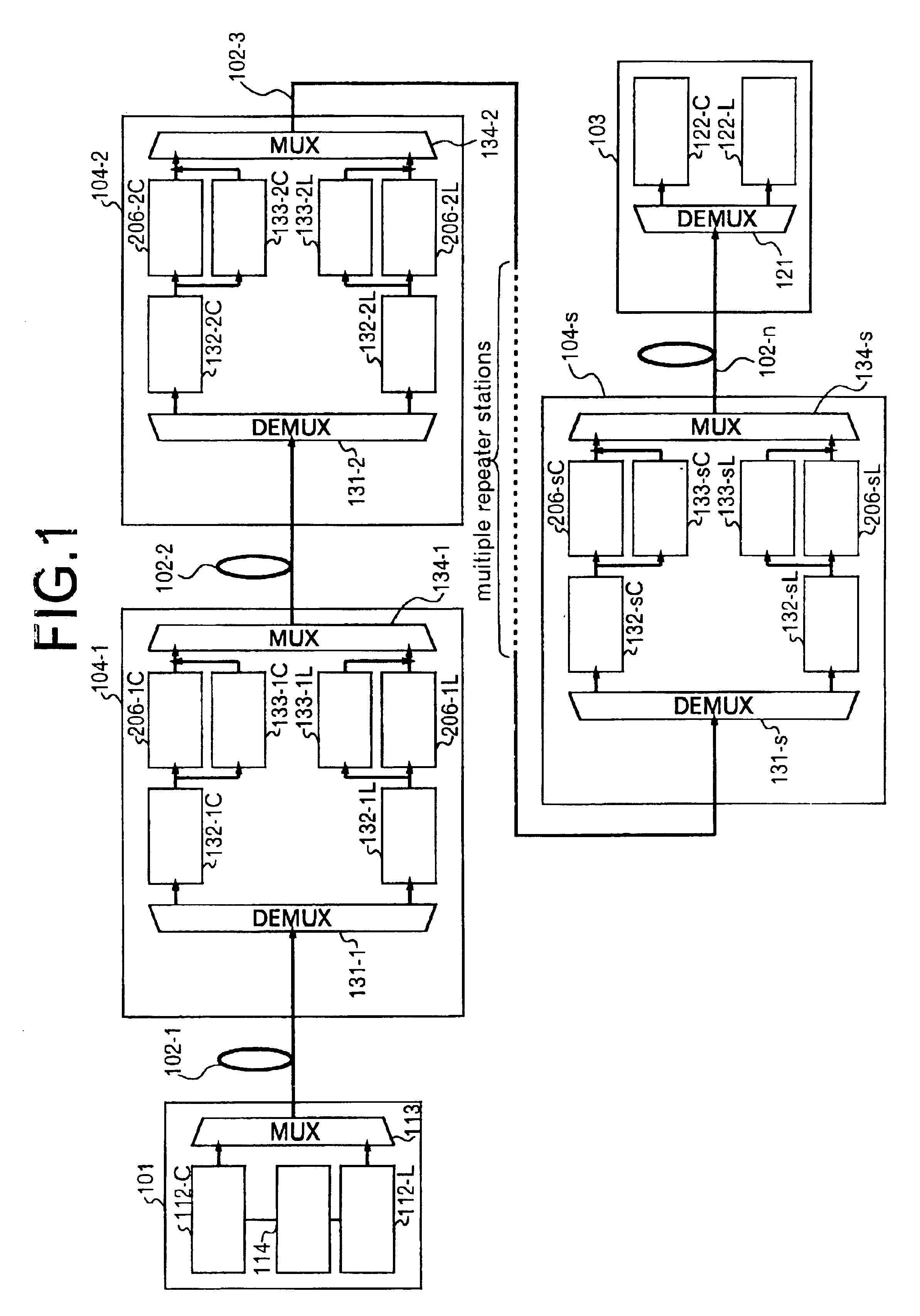
Next, a method of activating an optical communication system when the optical communication system according to the first embodiment is installed afresh or when any change occurs in the optical communication system such as addition of the optical repeater station(s) 104 will be explained.

FIG. 6 is a flowchart when the optical communication system according to the first embodiment is activated.

The operator instructs the system management part 114 to activate the optical communication system.

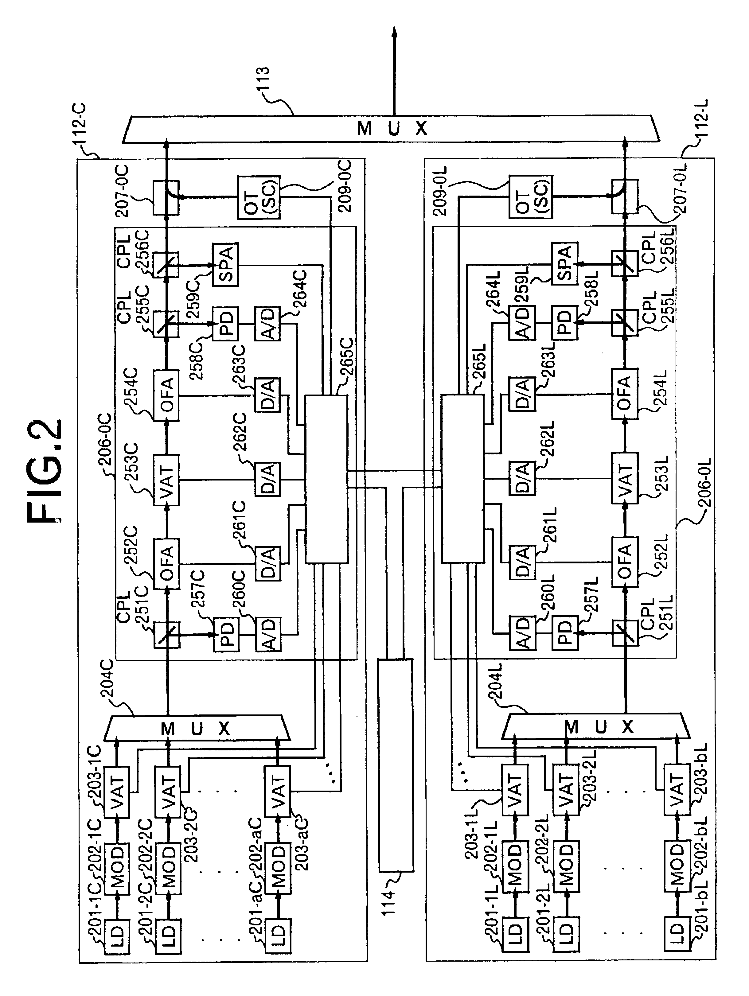
Referring to FIG. 6, the system management part 114 oscillates and stably operates laser diodes 201-1C to 201-aC as the light sources (S1).

Generally, the oscillation wavelength of laser diode deviates from a predetermined value immediately after oscillation due to transient characteristics. The laser diode is allowed to operate stably by stabilizing the device temperature of the laser diode 201 and its driving current.

The system management part 114 gives ...

second embodiment

[Operation and Effect of Second Embodiment]

Next, the explanation will be given on the activation method of the optical communication system of the second embodiment when the optical system is installed afresh or when any change occurs in the optical communication system such as the addition of the optical repeater station 108.

The second embodiment includes the Raman amplification part 136 for amplifying the WDM optical signals of the two wavelength bands by utilizing the induced Raman scattering phenomenon. Therefore, the system management part 114 activates the optical communication system in the following way.

FIG. 13 is a flowchart (No. 1) of activating the optical communication system according to the second embodiment.

FIG. 14 is a flowchart (No. 2) of activating the optical communication system according to the second embodiment.

The operator instructs the system management part 114 to activate the optical communication system.

Referring to FIGS. 13 and 14, the operations conducte...


PUM

PropertyMeasurementUnit
wavelengthsaaaaaaaaaa
wavelength bandaaaaaaaaaa

Abstract

The invention relates to a method of activating an optical communication system comprising a plurality of optical amplifiers having an optical amplifier, between optical transmission lines in which wavelength-division multiplex optical signals are transmitted. The method comprises steps of: generating a desired slope in a desired wavelength range of a gain wavelength curve of the optical amplifier; adjusting an output of the optical amplifier to a desired output level; performing the above two steps in a plurality of optical repeater stations, the steps being carried out in sequence from the first to the last optical repeater stations; and adjusting a level in each optical signal in the wavelength-division multiplex optical signal so as to have substantially constant optical signal-to-noise ratios in the optical signals to be received. Activating the optical communication system according to this procedure allows proper execution of gain slope compensation, output control, and pre-emphasis control.

Description

BACKGROUND OF THE INVENTION1. Field of the InventionThis invention relates to an activation method of an optical communication system and a channel increasing / decreasing method. More particularly, this invention relates to an activation method of an optical communication system for executing gain slope compensation, output control and pre-emphasis control, and its channel increasing / decreasing method. This invention further relates to a computer-readable recording medium for causing a computer to execute a program of such an activation method and such a channel increasing / decreasing method.2. Description of the Related ArtMulti-media communication typified by the Internet has spread drastically in recent years. Research and development of optical communication technologies for achieving ultra-long distance communication and larger capacity communication has been made intensively in the field of communication technologies so as to cope with the drastic increase of traffic due to the ...

Claims


Application Information

Patent Timeline
Patent Type & Authority Patents(United States)
IPC IPC(8): H04J14/02H04B10/17H04B10/07H04B10/29H04B10/293H04B10/296H04B10/564H04B10/572
CPCH04B10/2942H04J14/0221H04J14/0213H04J14/021H04B2210/258
Inventor TSUDA, TAKASHIYAMANE, KAZUOMURAKAMI, MAKOTOSHIMA, TOORUMATSUMOTO, TOORUIWAKI, HIROYUKIIMAI, KAZUTO
Owner FUJITSU LTD
Why Eureka
Try Eureka