
Bone measuring method

a measurement method and bone technology, applied in the field of bone measurement method, can solve the problems of difficult to specify the boundaries between the bones, and achieve the effects of accurate evaluation and measurement of three-dimensional bone-related information, high speed, and good repeatability

Inactive Publication Date: 2005-01-04
TEIJIN LTD
View PDF9 Cites 35 Cited by
  • Summary
  • Abstract
  • Description
  • Claims
  • Application Information

AI Technical Summary

Benefits of technology

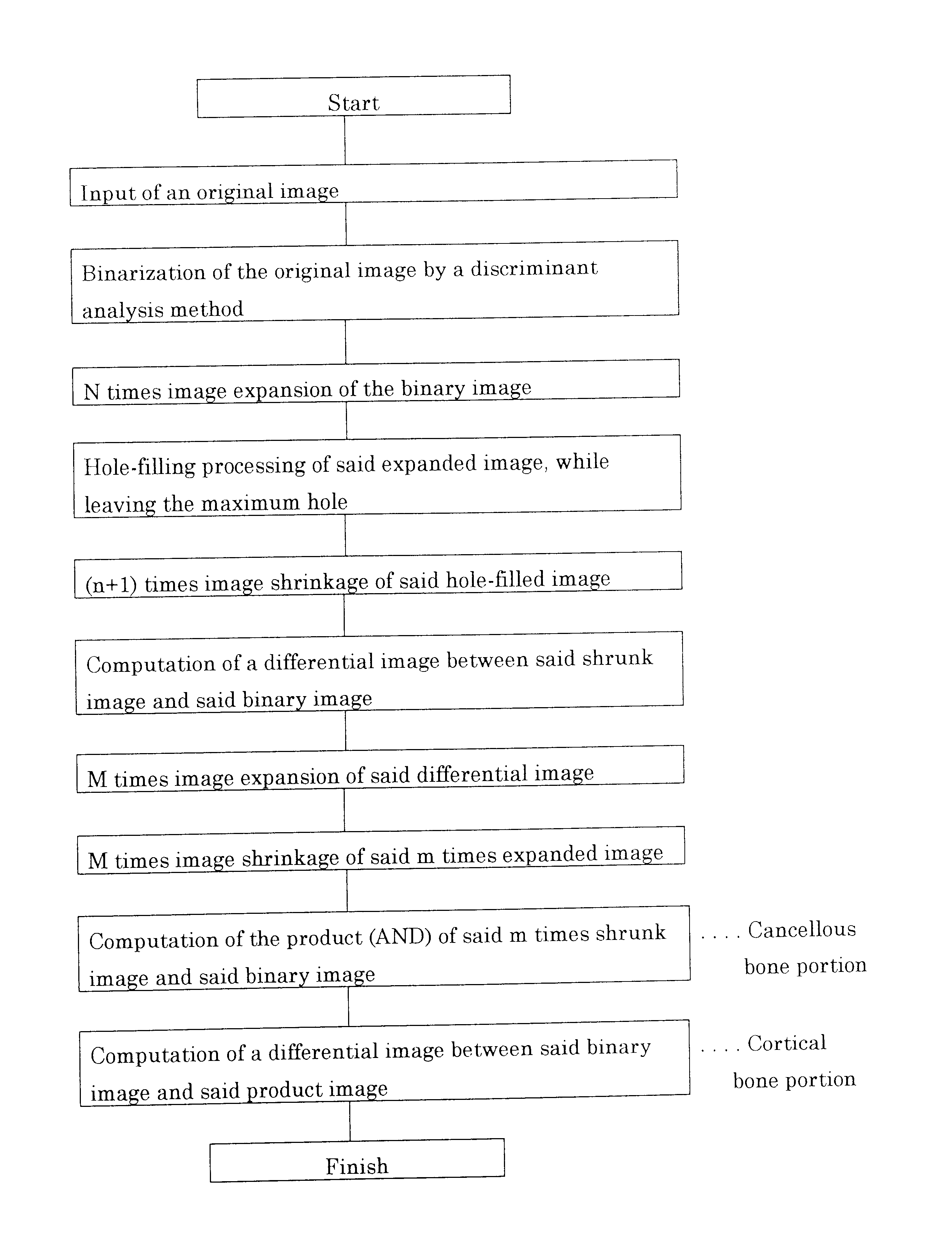
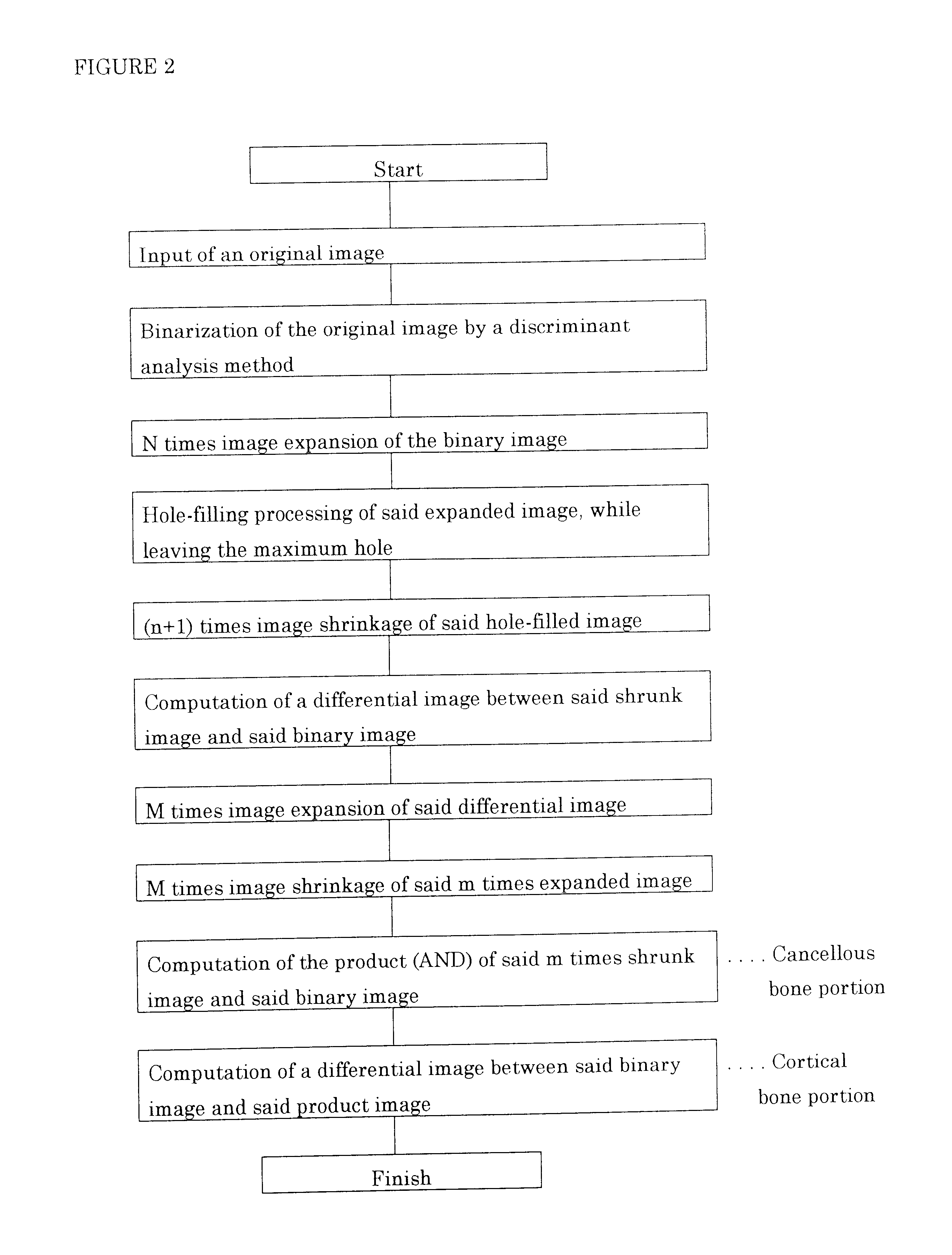
The present invention was achieved by finding out that the template image enables the extraction of the whole bone portion and thereby the separation of the cortical bone from the cancerous bone in good repeatability and further that the extraction step enables high speed processing to achieve the purpose, because of being composed of a highly simple algorithm.
Thus, the present invention enables the more accurate evaluation of the three-dimensional bone-related information than those by other methods, because the separated cortical bone portion three-dimensional image and the separated cancellous bone portion three-dimensional image can non-invasively and automatically be extracted at a high speed in good repeatability.
Thus, by the present invention, the boundary surface images between the separated cortical bone and the separated cancellous bone can non-invasively and automatically be extracted at a high speed and in good repeatability, thereby enabling the more accurate evaluation and measurement of the three-dimensional bone-related information.

Problems solved by technology

The cortical bones are mostly structurally continued to the cancellous bones, and it is difficult to specify the boundaries between both the bones.
However, the method includes a case that the cortical bone portion or the cancerous bone portion is divided, whereby a problem may be caused, when a plurality of test bones are compared with each other by the method.

Method used


Image

  • Bone measuring method
  • Bone measuring method
  • Bone measuring method

Examples


Embodiment Construction

The present invention will sequentially be explained together with the form of the execution of the invention on the basis of an example applied to the lumber vertebra of a rat as follows. An example for the femur of a rat will also be described, and it will further be showed that the invention can also be applied to a long bone.

(1). Bone measurement method by which a cortical bone and a cancellous bone can be separated from each other

The cross sections of a rat lumber vertebra as a test bone were scanned using a microfocused X-ray computed tomographic apparatus (hereinafter referred to as “μX-ray CT”) having a focal size and a resolution sufficient for measuring the fine structures of the cancellous bone as a scanning means, similarly as the above-described JP-A No. 9-294740. An apparatus for generating two-dimensional information, such as a high resolution X-ray apparatus, a nuclear magnetic resonance imaging diagnostic apparatus (MRI) or a film scanner, may also be applied to the...


PUM


Abstract

This invention relates to a bone measurement method for measuring a bone shape, structure and architecture on the basis of the tomographic images of a test bone or joint, in more detail, to a bone measurement method characterized by having a template image extraction step for obtaining a wholly continued template image of a bone inner portion surrounded by a cortical bone from the binary image of a test bone cross section, and separating a cortical bone and a cancellous bone by the product of said template image and said binary image, as a bone measurement method which enables the automatic, high-speed and repeatable separation of a cortical bone and a cancellous bone on the basis of the binary image of a test bone or joint cross section and by which a separated three-dimensional image of the cortical bone portion and the cancellous bone portion is obtained as the bases for a non-invasive analyses of three-dimensional bone structure, bone strength, and the like.

Description

TECHNICAL FIELDThe present invention relates to a bone measurement method for measuring a bone shape, structure and architecture on the tomographic images of a test bone or joint, in more detail, to a bone measurement method for separating a cancellous bone and a cortical bone on the basis of the binary images of a test bone or joint cross section, enabling the automatic, high-speed and repeatable separation of the cortical bone and the cancellous bone, and giving the separated three-dimensional images of the cortical bone portion and the cancellous bone portion as the bases for the non-invasive analyses of three-dimensional bone structure, bone strength, and the like. Further, the present invention relates to a bone measurement method which comprises applying a method (advanced Marching Cube method) for defining the boundary surface of an object to a separated cross section (hereinafter referred to as “connected surface”) in the separated three-dimensional images of the cortical bo...

Claims


Application Information

Patent Timeline
Patent Type & Authority Patents(United States)
IPC IPC(8): A61B6/00
CPCA61B6/505Y10S128/922
Inventor AZUMA, YOSHIAKIHARADA, YOSHIFUMIYAMADA, NORIHIROMAEDA, TSUTOMUOHTA, TOMOHIRO
Owner TEIJIN LTD
Learn More