System and method for acquiring data

a data acquisition and data technology, applied in the field of data acquisition, can solve the problems of reducing the clarity of display, affecting the efficiency of data acquisition, and difficulty in displaying the different parameters in a concise and synchronised way, so as to improve the clarity of display and facilitate portability without risk of damage

Inactive Publication Date: 2005-01-04
ISIS INNOVATION LTD
View PDF14 Cites 308 Cited by
  • Summary
  • Abstract
  • Description
  • Claims
  • Application Information

AI Technical Summary

Benefits of technology

Preferably the system is based around a data processing device, which incorporates the master clock, the time stamping means and the display, and the system may be ruggedized so as to be easily portable without risk of damage.
To improve the clarity of the display the data may be displayed selectively on one of two different timescales which may be referred to as a

Problems solved by technology

Thus the output signals from the devices may not be synchronised and may be at widely differing rates.
However, because all are measured at different rates, and typically by different pieces of apparatus with respective system clocks within them, displaying the different parameters together in a concise and synchronised way is difficult.
However, this requires that all of the monitors are, in essence, integrated which is expensive and inflexible, and further this makes existing equipment redundant.
The disp

Method used


Image

  • System and method for acquiring data
  • System and method for acquiring data
  • System and method for acquiring data

Examples


Embodiment Construction

An embodiment of the invention will be described applied to the monitoring of physiological parameters, though the invention can be applied to any system being monitored by devices running on independent clocks. Typical examples include vehicles, manufacturing or processing plants, control or monitoring systems for instance for the environment.

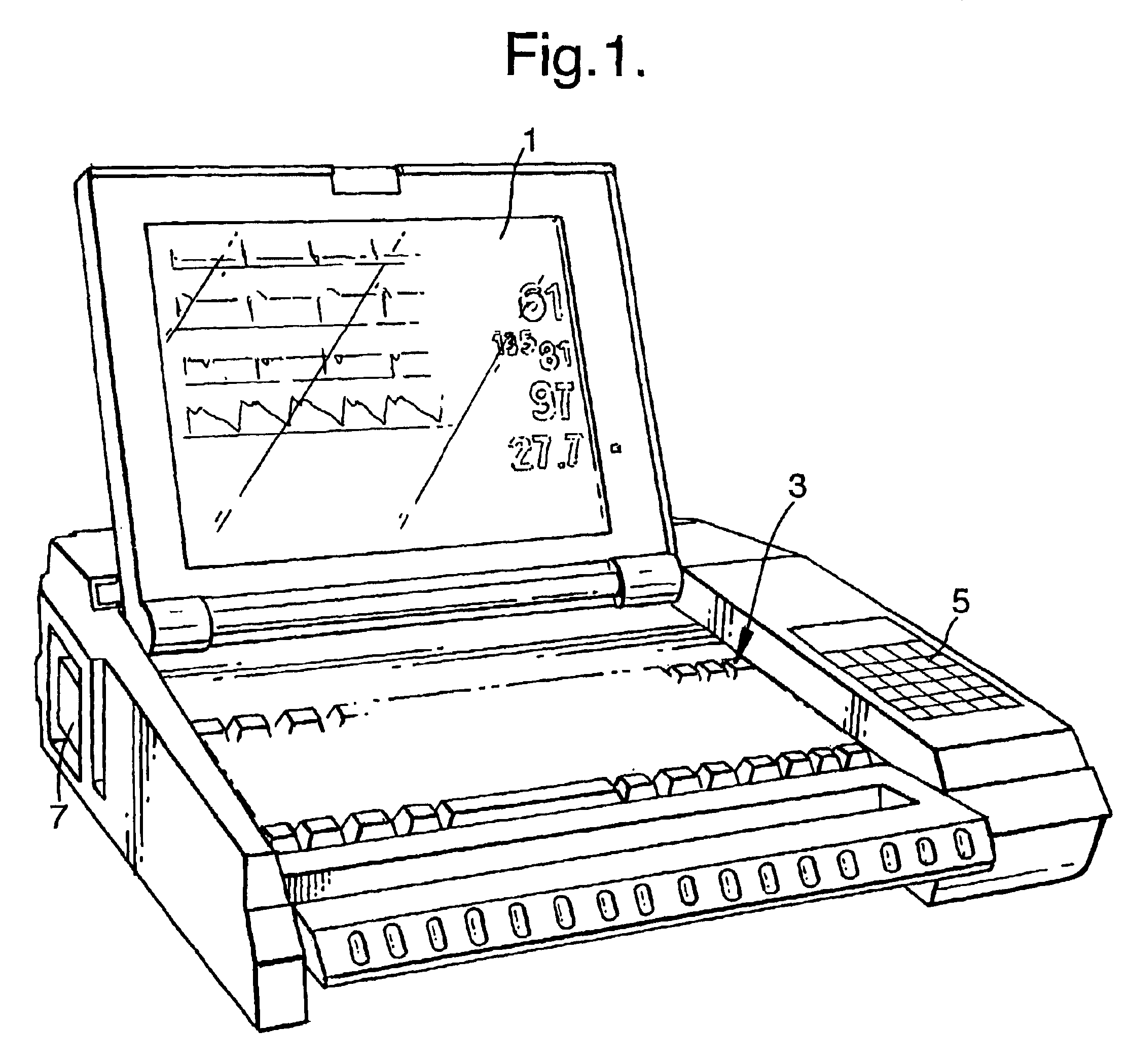
Referring to FIG. 1 the illustrated embodiment of the invention is based on a ruggedized laptop computer which includes a display (1) a keyboard (3) and touchpad (5) as data input devices and connectors (7) to which can be connected the various types of data collection device from which physiological data is to be acquired.

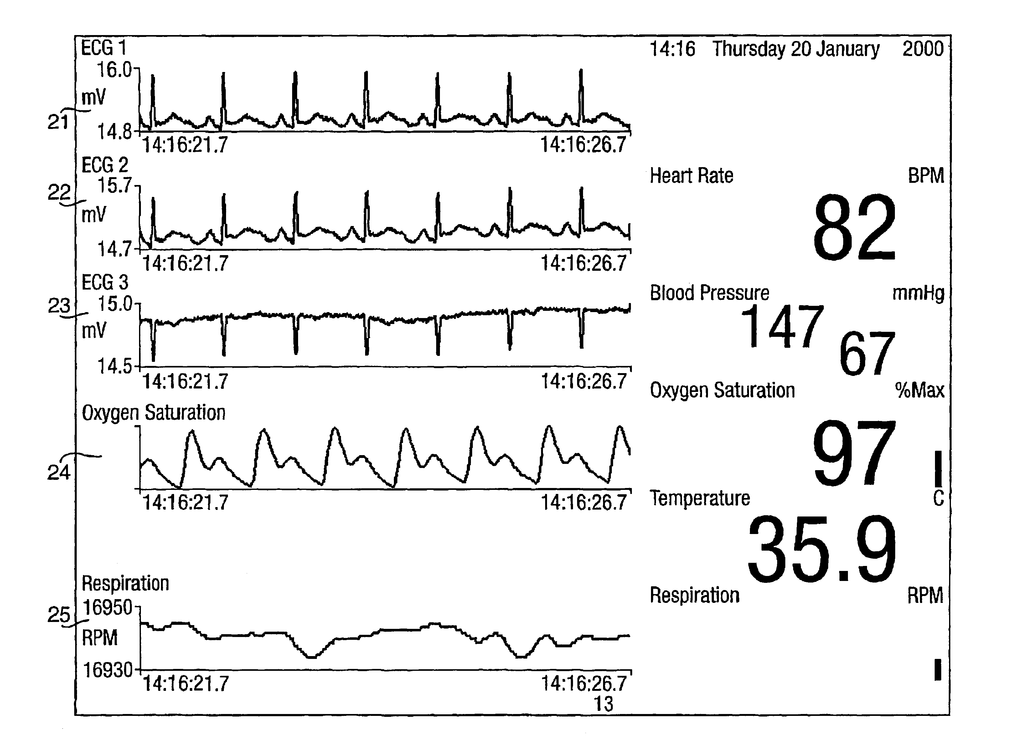
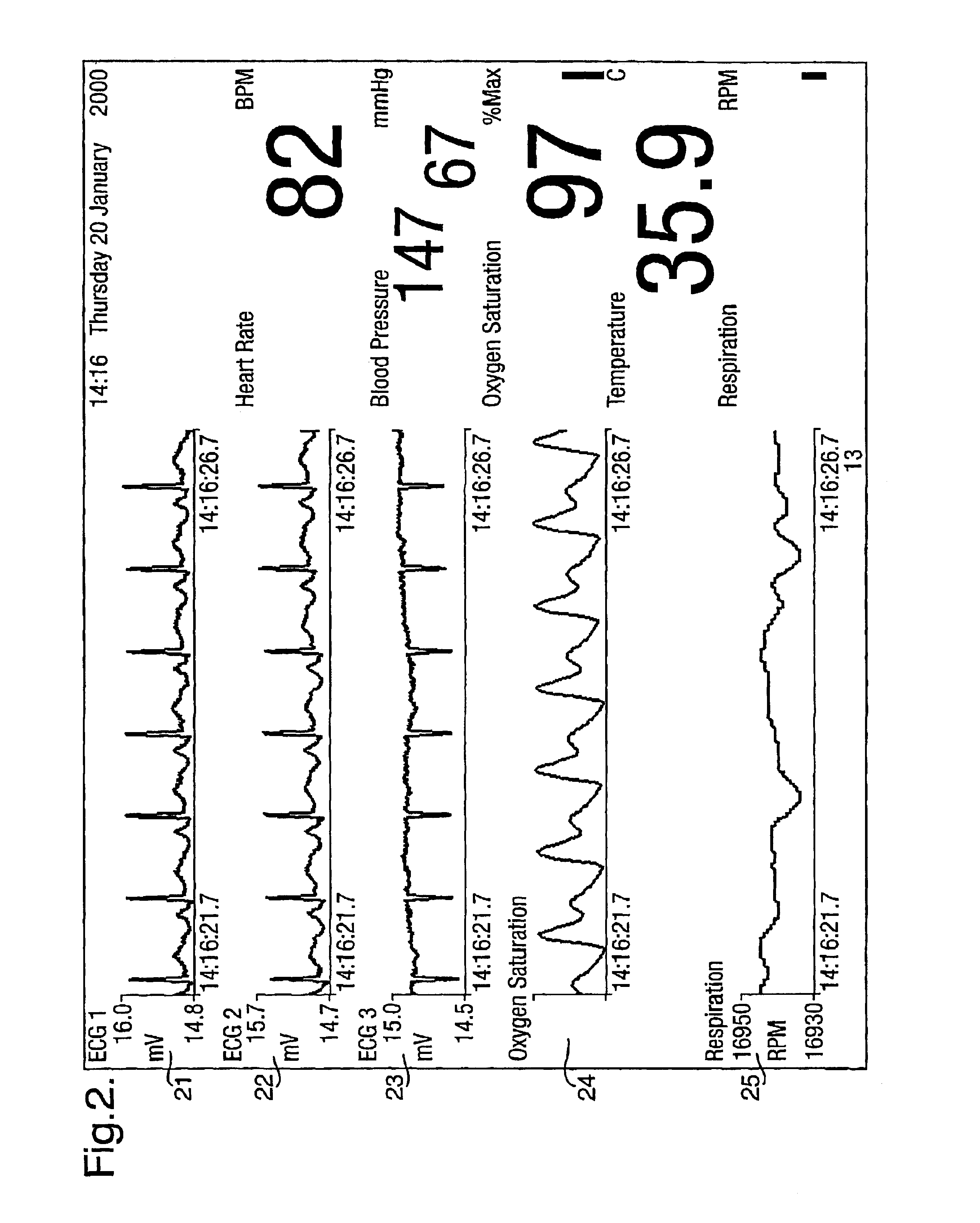
This embodiment of the invention is suitable for receiving signals from such devices as an electrocardiograph, blood pressure monitor, respiration monitor, oxygen saturation monitor and thermometer and, as will be appreciated from the discussion above, typically all of these signals are acquired by those devices at different...


PUM


Abstract

A system for acquiring, and displaying, data such as physiological data, from a plurality of data connection devices, each of which monitor one or more different parameters and output data at different sampling frequencies based on their own system clocks. The system receives the data signals at different sampling frequencies and associates each sample of each signal with a time stamp derived from a single master clock. Low rate and high rate data are treated differently. Low rate data is associated with the current value of the master clock, where as high rate data is time stamped by giving the first sample a time stamp equal to the current value of the current master clock, subsequent samples being given an estimated time stamp based on the expected interval between samples derived from the sampling frequency of the data collection device, and the timescale given to the first example. The estimated time stamp may be periodically corrected, and the estimation calculation can be improved by correcting the value used for the interval between samples. The different signals can be displayed together on a display aligned with respect to a time axis. The system can display, the data in two different timescales, one showing a few seconds of data and one showing a few hours of data. The data traces are scrolled across the time axis, new data being added to one end of the trace.

Description

TECHNICAL FIELDThis invention relates to the acquisition of data from a plurality of data collection devices each monitoring one or more different parameters, and in particular to the synchronisation of that data.BACKGROUND AND SUMMARYThere are many different situations in which a system is monitored by a plurality of sensors. Often such sensors are part of different data collection devices, and monitor the same or different parameters of the system. In this situation each of the data collection devices may include its own clock controlling the sampling of the data signal it is monitoring. These clocks may be free running with respect to each other. Thus the output signals from the devices may not be synchronised and may be at widely differing rates.For instance, it is normal when monitoring the condition of a patient to monitor a variety of physiological parameters such as the electrocardiogram (which can be multiple channel), blood pressure, respiration, oxygen saturation using pu...

Claims


Application Information

Patent Timeline
IPC IPC(8): G06F19/00A61B5/00
CPCA61B5/02055G06F19/322A61B5/021A61B5/044G06F19/3406A61B5/145A61B5/0816A61B5/742G16H40/63G16H10/60A61B5/339
Inventor TARASSENKO, LIONELTOWNSEND, NEIL WILLIAM
Owner ISIS INNOVATION LTD
Why Eureka
Try Eureka