High performance heat exchange assembly

Inactive Publication Date: 2005-01-11
DELPHI TECH INC
View PDF34 Cites 27 Cited by
  • Summary
  • Abstract
  • Description
  • Claims
  • Application Information

AI Technical Summary

Benefits of technology

A range of new heat sinks for electrical and electronic components is herein presented that provides for space-efficient heat exchange with low

Problems solved by technology

However, there are limitations to achievable fin densities based upon manufacturing constraints and cooling fluid flow requirements.
Until rec

Method used


Image

  • High performance heat exchange assembly
  • High performance heat exchange assembly
  • High performance heat exchange assembly

Examples


example 1

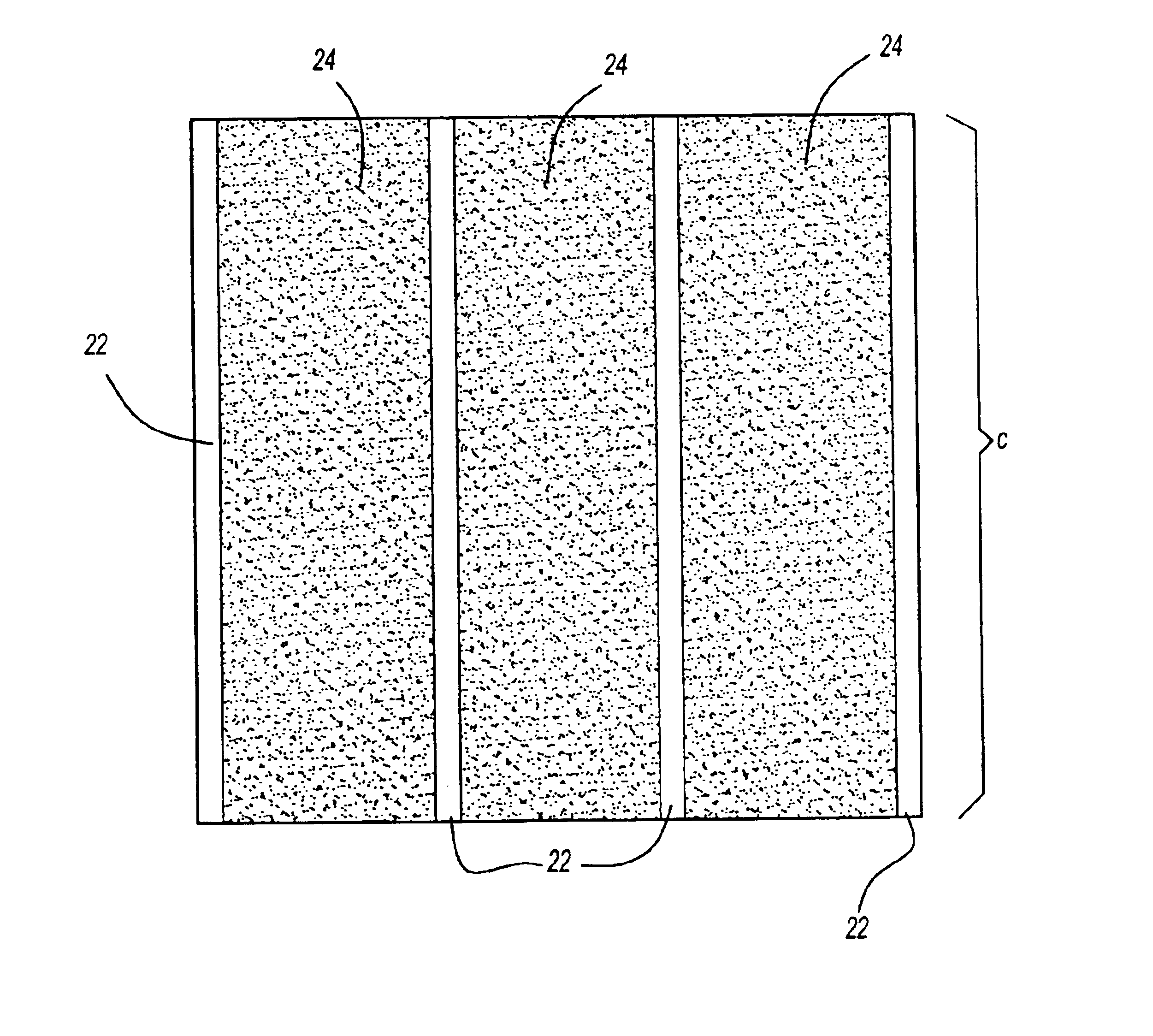
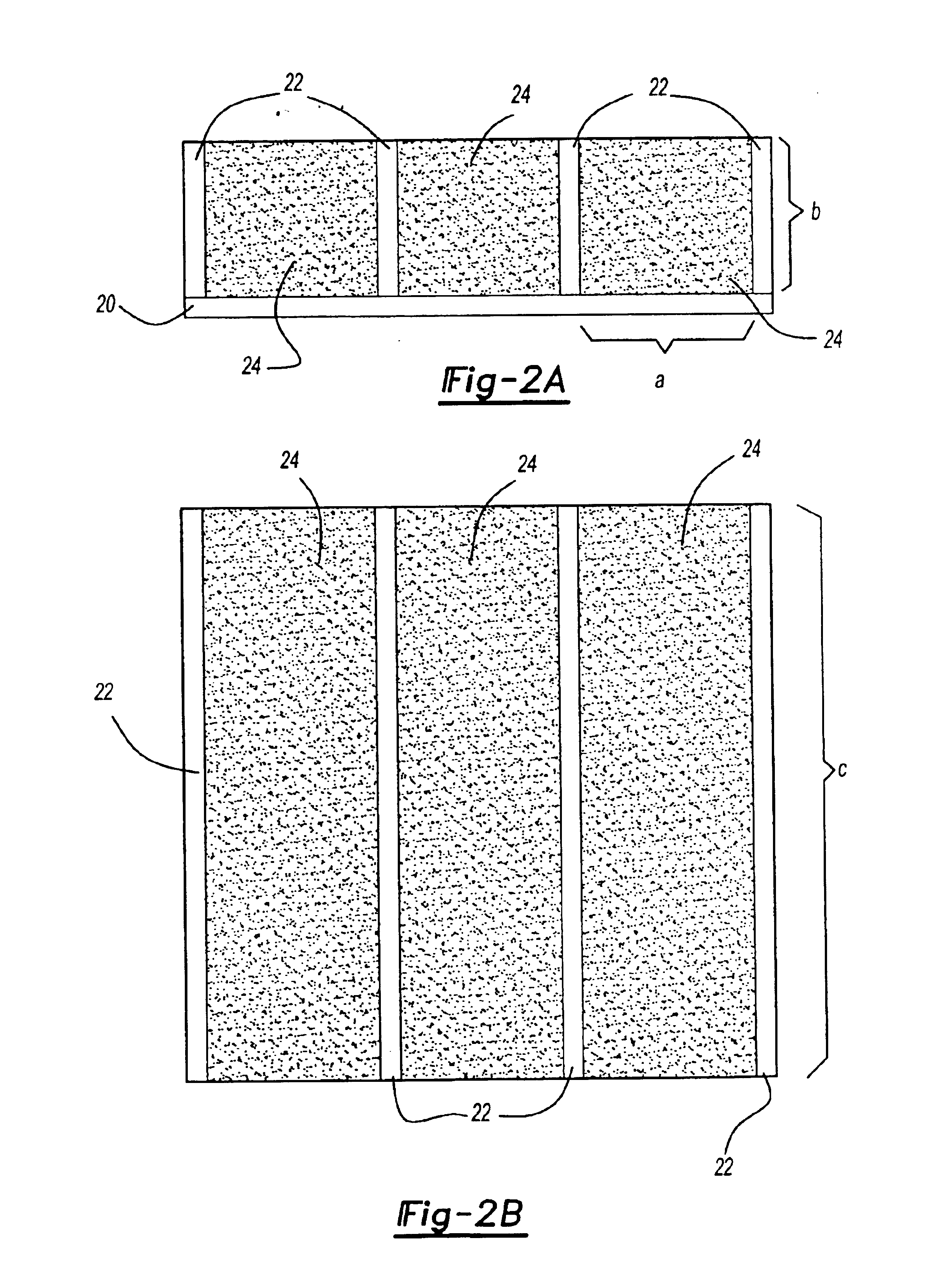
In a heat sink of the present invention, aluminum fins are selected having a thickness δf=0.125 inch (0.0104 ft) with thermal conductivity kf=133 Btu / ft hr° F. (0.0369 Btu / ft s ° F.). The fin length c in the flow direction, dictated by the packaging and heat dissipation consideration, is 4 inches (0.3333 ft). A commercially available open cell aluminum foam with linear density of n=20 pores per inch (240 pores / ft) and a porosity φ=0.90 is also selected. The cooling medium is ambient air flowing with a mean velocity um=10 ft / s. The transport properties of the ambient air are as follows:Density ρ=0.0749 lbm / ft3 Thermal conductivity k=0.0000041 Btu / ft s ° F.Isobaric specific heat cp=0.2410 Btu / lbm° F.Dynamic viscosity μ=0.0000123 lbm / ft s

To determine optimum fin height b, the convective heat transfer coefficient h is first determined using Equation (2), above, providing h=0.0313 Btu / ft2s ° F. Next, introducing this value of h into Equation (1), above, we obtain the optimum fin height b...

example 2

This example is the same as Example 1 except that the fin material has been changed from aluminum to copper. The copper fins have a thickness δf=0.125 inch (0.0104 ft) and thermal conductivity kf=226 Btu / ft hr ° F. (0.0628 Btu / ft s ° F.). The fin length c in the flow direction, dictated by the packaging and heat dissipation consideration, is 4 inches (0.3333 ft). The reticulated foam is a commercially available open cell aluminum foam having a linear density n=20 pores per inch (240 pores / ft) and a porosity φ=0.90. The cooling medium is ambient air flowing with a mean velocity um=10 ft / s. The transport properties of the ambient air are as follows.Density ρ=0.0749 lbm / ft3 Thermal conductivity k=0.0000041 Btu / ft s ° F.Isobaric specific heat cp=0.2410 Btu / lbm° F.Dynamic viscosity μ=0.0000123 lbm / ft s

As in Example 1, using Equation (2), the convective heat transfer coefficient h=0.0313 Btu / ft2 s ° F. Then, using Equation (1), we obtain the optimum fin height b=0.0939 ft (1.1271 inch). T...


PUM

PropertyMeasurementUnit
Volumeaaaaaaaaaa
Electrical conductoraaaaaaaaaa
Heataaaaaaaaaa

Abstract

Heat sinks are provided that achieve very high convective heat transfer surface per unit volume. These heat sinks comprise a spreader plate, at least two fins and at least one porous reticulated foam block that fills the space between the fins.

Description

TECHNICAL FIELDThe present invention is directed to heat sinks primarily for use in dissipating waste heat generated by electrical and / or electronic components and assemblies. These heat sinks include a heat spreader plate and an assembly of heat conducting fins and reticulated foam structures that are bonded together. Electronic components are connected to one surface of the spreader plate with the assembly of fins and foam connected to another surface of the spreader plate in contact with a cooling fluid.BACKGROUND OF THE INVENTIONHigh power electrical and electronic components continue to have an increasing demand for higher power dissipation within a relatively confined space. In order to provide for such higher power dissipation requirements while remaining suitably compact, several levels of thermal management are usually required at the device, sub-assembly and component level.At the component level, various types of heat exchangers and heat sinks have been used that apply na...

Claims


Application Information

Patent Timeline
IPC IPC(8): F28F3/00F28F13/00F28F3/02H01L23/373H01L23/367H01L23/34
CPCF28F3/02F28F13/003H01L23/367H01L23/3677H01L23/3733Y10T29/49393Y10S165/907H01L2924/0002Y10S165/905H01L2924/00
Inventor EESLEY, GARY LYNNMORELLI, DONALD T.BHATTI, MOHINDER SINGH
Owner DELPHI TECH INC
Why Eureka
Try Eureka