Substrate processing apparatus equipping with high-pressure processing unit

a processing apparatus and high-pressure technology, applied in lighting and heating apparatus, charge manipulation, furnaces, etc., can solve the problems of destroying fine patterns, reducing the size of semiconductor devices, and new problems in the processing of substrates

Inactive Publication Date: 2005-01-11
DAINIPPON SCREEN MTG CO LTD
View PDF16 Cites 33 Cited by
  • Summary
  • Abstract
  • Description
  • Claims
  • Application Information

AI Technical Summary

Benefits of technology

A main object of the present invention is to ensure, within a substrate processing apparatus in which main transportation means transports a subs

Problems solved by technology

By the way, while the sizes of patterns of semiconductor devices have been rapidly reduced over the recent years, these endeavors have led to a new problem to processing of substrates.
During the drying process among these processes, if the interface between the rinsing fluid and a gas appears on the substrate W as drying proceeds and if this interface shows itself in a gap between the fine patterns of the semiconductor device, the surface tension of the rinsing fluid pulls the fine patterns toward each other and accordingly destroys the fine patterns, which is a problem.
However, in the event that all or some of the processing units are formed by the proposed apparatus, there are following problems.
In other words, a corrosive chemical agent, such as strong acid and strong alkali, can not be introduced for execution of surface treatments although a pressure vessel needs be used as the container, and therefore, the range of selection of chemical agents is drastically restricted.
This is because a pressure vessel is mainly made of a metallic material considering the resistance against pressure and because strong acid or alkali corrodes a surface of the pressure vessel which is exposed to a chemical fluid.
While an obvious solution is to coat an inner surface of the pressure vessel with a corrosion-resistant coat such as a fluorocarbon resin, it is virtually difficult to keep the coating continuously exhibiting this function under a high pressure over a long period of time.
Further, even if the inner surface of the pressure vessel is coated with a corrosion-resistant coat, it is very difficult to coat in

Method used


Image

  • Substrate processing apparatus equipping with high-pressure processing unit
  • Substrate processing apparatus equipping with high-pressure processing unit
  • Substrate processing apparatus equipping with high-pressure processing unit

Examples


Embodiment Construction

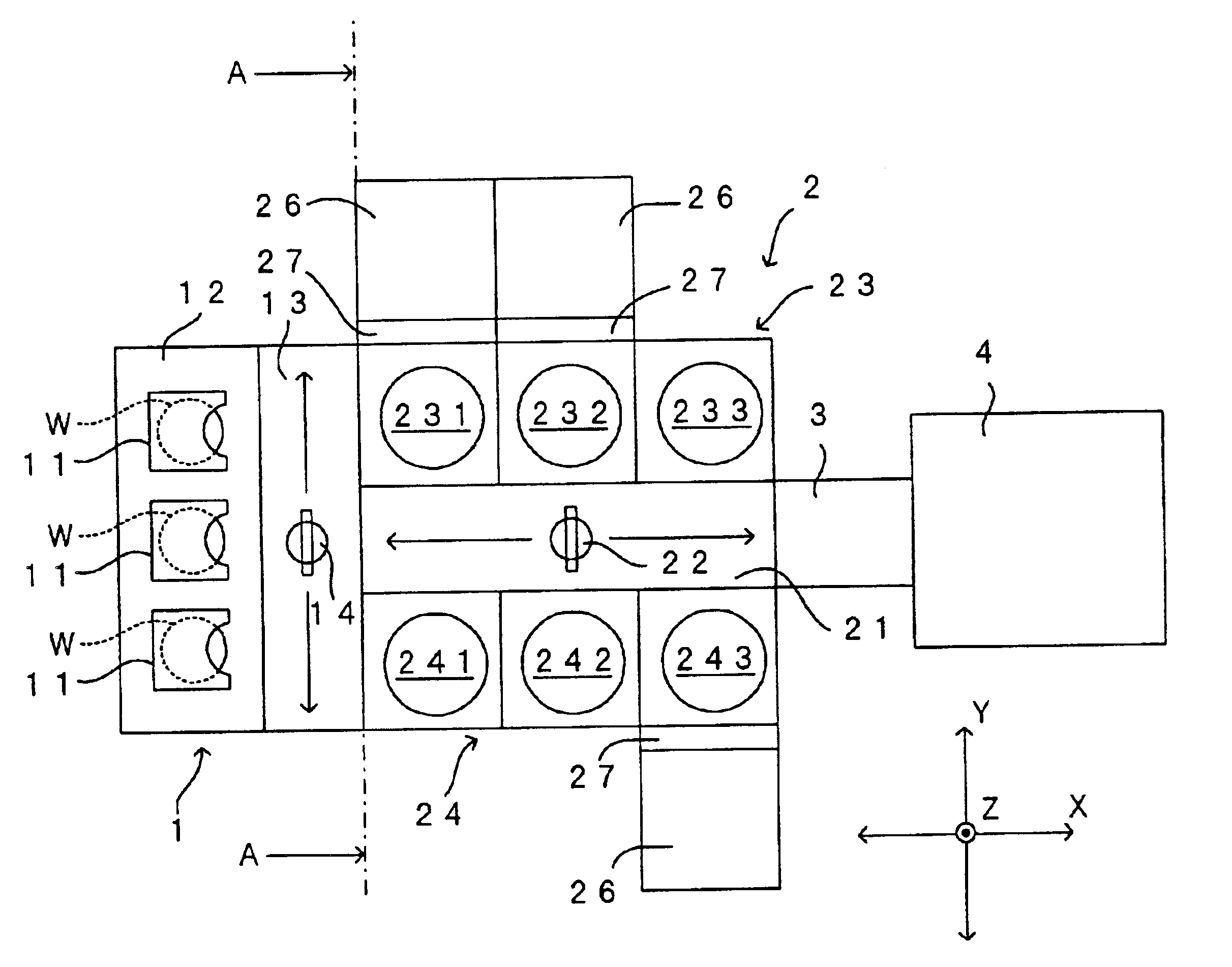
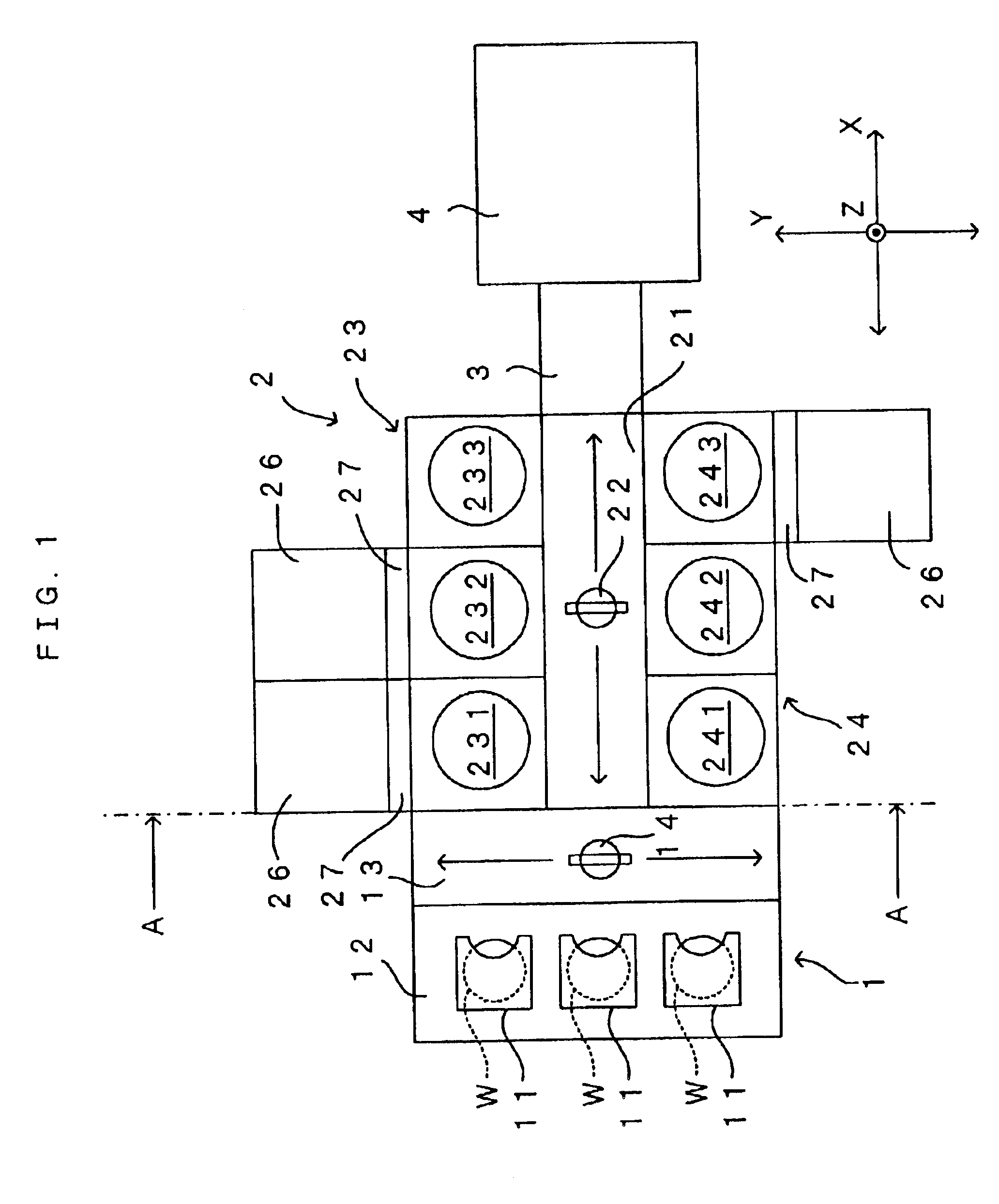
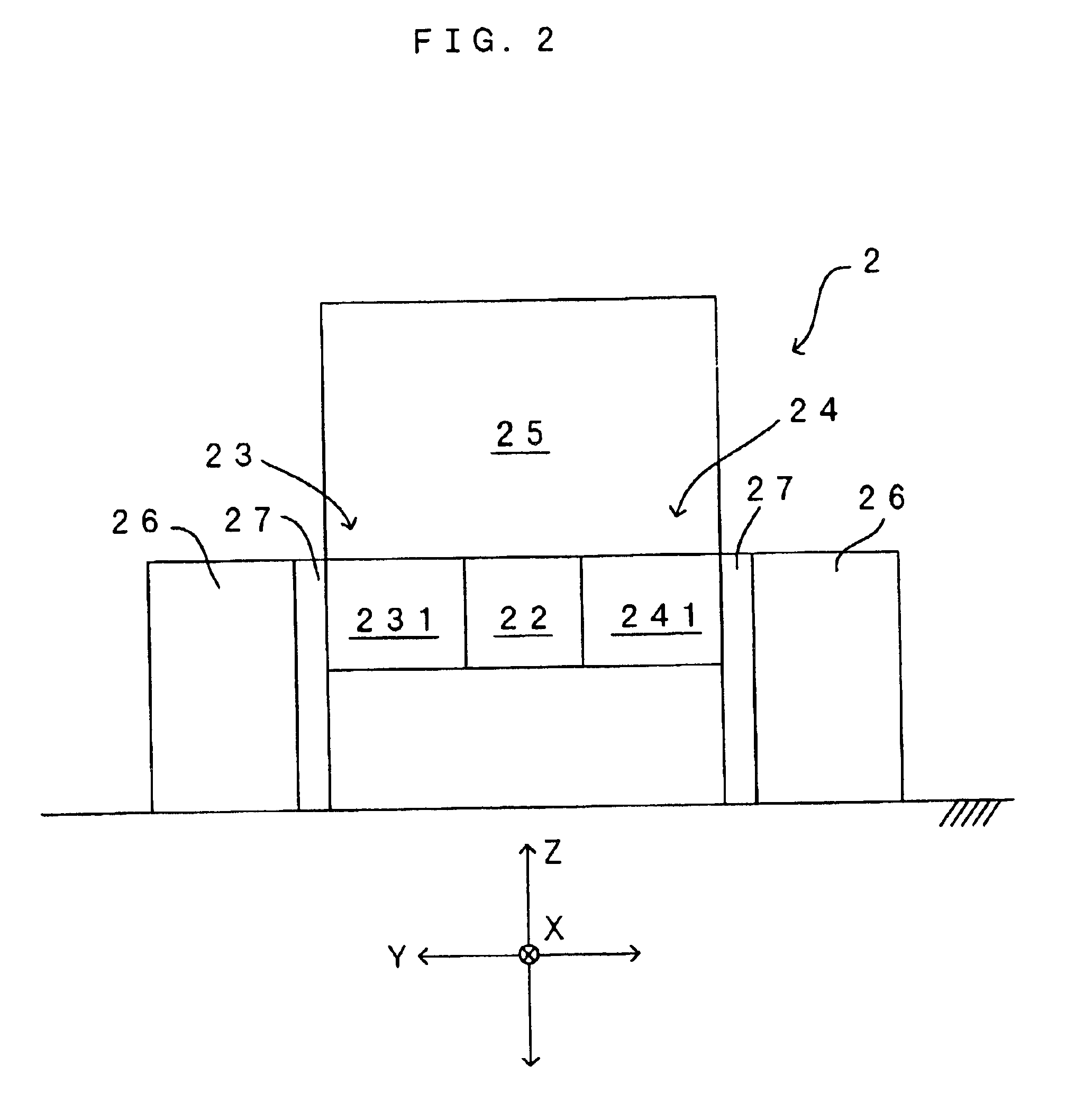
FIG. 1 is a drawing which shows a preferred embodiment of a substrate processing apparatus according to the present invention. FIG. 2 is a drawing along the A—A line in FIG. 1. Disposed in this substrate processing apparatus are an indexer 1, a processing module 2 which is disposed adjacent to and on one side to the indexer 1, an interface 3 which is disposed adjacent to and on one side to the processing module 2, and an exposing unit 4 which is disposed adjacent to and on one side to the interface 3. Of these elements, the indexer 1 is exactly the same in structure to that of the conventional apparatus shown in FIG. 9, and therefore, the same structures will be denoted at the same reference symbols but will not be described again.

As in the conventional apparatus shown in FIG. 9, the processing module 2 comprises a main transportation robot 22 which can move on a main transportation path 21 which extends long along a direction X perpendicular to the direction Y, and unit columns 23,...


PUM

PropertyMeasurementUnit
Pressureaaaaaaaaaa

Abstract

With respect to any one of processing units, a main transportation path, a developing unit, a dedicated transportation robot and a high-pressure processing unit are disposed linearly in this order in a direction. Hence, even if a processing fluid adhering to a substrate or an evaporant of the processing fluid moves toward the main transportation path while the high-pressure processing unit transports the substrate wet with the processing fluid, there are the processing units located which the processing fluid or its evaporant must arrive at before reaching the main transportation path.

Description

BACKGROUND OF THE INVENTION1. Field of the InventionThe present invention relates to a substrate processing apparatus which performs a variety types of surface treatments (e.g., development, etching, cleaning, rinsing, drying) upon a variety types of substrates such as a semiconductor wafer, a glass substrate for photomask, a glass substrate for liquid crystal display, a glass substrate for plasma display and an optical disk substrate (hereinafter simply referred to as “substrates”).2. Description of the Related ArtA substrate processing apparatus which is shown in FIG. 9, for instance, has been proposed as this type of substrate processing apparatus. Disposed in the illustrated substrate processing apparatus are an indexer 1 and a processing module 2 which is disposed adjacent to and on one side to the indexer 1. The indexer 1 comprises a cassette mounting stage 12 which mounts a plurality of cassettes 11 each capable of housing more than one substrates W, and an indexer robot 14 w...

Claims


Application Information

Patent Timeline
IPC IPC(8): C03C15/00C03C23/00H01L21/00G03F7/30B65G49/07G03F7/40H01L21/027H01L21/304
CPCC03C15/00C03C23/0075H01L21/67173H01L21/67161C03C23/0085H01L21/00
Inventor IWATA, TOMOMIMURAOKA, YUSUKESAITO, KIMITSUGUMIZOBATA, IKUOMIYAKE, TAKASHIKITAKADO, RYUJI
Owner DAINIPPON SCREEN MTG CO LTD
Why Eureka
Try Eureka