
Multilayer structured quartz glass crucible and method for producing the same

a technology of quartz glass and structured quartz, which is applied in the direction of glass production, ceramic containers, rigid pipes, etc., can solve problems such as productivity drop

Inactive Publication Date: 2005-01-11
HERAEUS QUARZGLAS +1
View PDF11 Cites 13 Cited by
  • Summary
  • Abstract
  • Description
  • Claims
  • Application Information

AI Technical Summary

Benefits of technology

The present invention relates to a multilayer structured quartz glass crucible for use in pulling up silicon single crystal. The crucible has a smooth inner surface and numerous fine pores inside it, which helps to homogenize the thermal conductance in case silicon is pulled up. The crucible is produced by a method involving forming an outer layer by molding and fusing a silicon dioxide powder inside a rotating mold, and then depositing a new layer of quartz glass inside the outer layer to create a double layered structure. The inner layer is made from a synthetic quartz glass, which has a low amount of impurities and is advantageous for pulling up silicon single crystal. However, the double layered crucible can still generate oscillation on the melt surface, causing difficulties in the operation of immersing a seed crystal and decreasing productivity. The present invention proposes a solution by reducing the temperature difference between the inner surface of the quartz glass crucible and the melt surface, which suppresses the reaction at the contact portion between the melt and the surface of the crucible and reduces the oscillation of the melt surface.

Problems solved by technology

When the melt surface causes oscillation, difficulties are found in the operation of immersing a seed crystal, and this requires a longer time for the so-called “seeding” operation, thereby resulting in a decrease in productivity, or leading to problems such as causing disordering to the single crystal ingot during its pulling up.

Method used


Image

  • Multilayer structured quartz glass crucible and method for producing the same
  • Multilayer structured quartz glass crucible and method for producing the same
  • Multilayer structured quartz glass crucible and method for producing the same

Examples


first embodiment

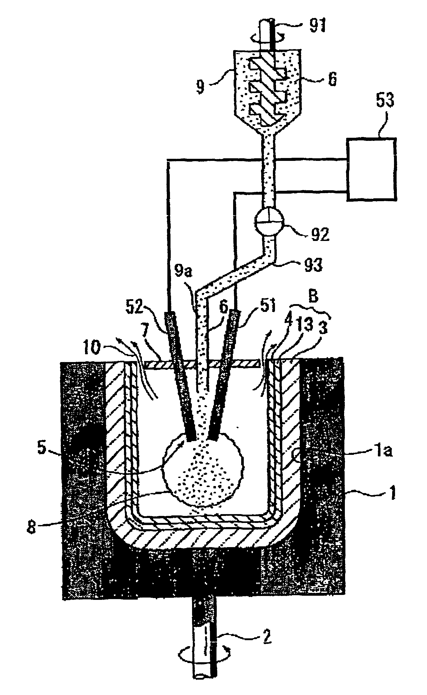
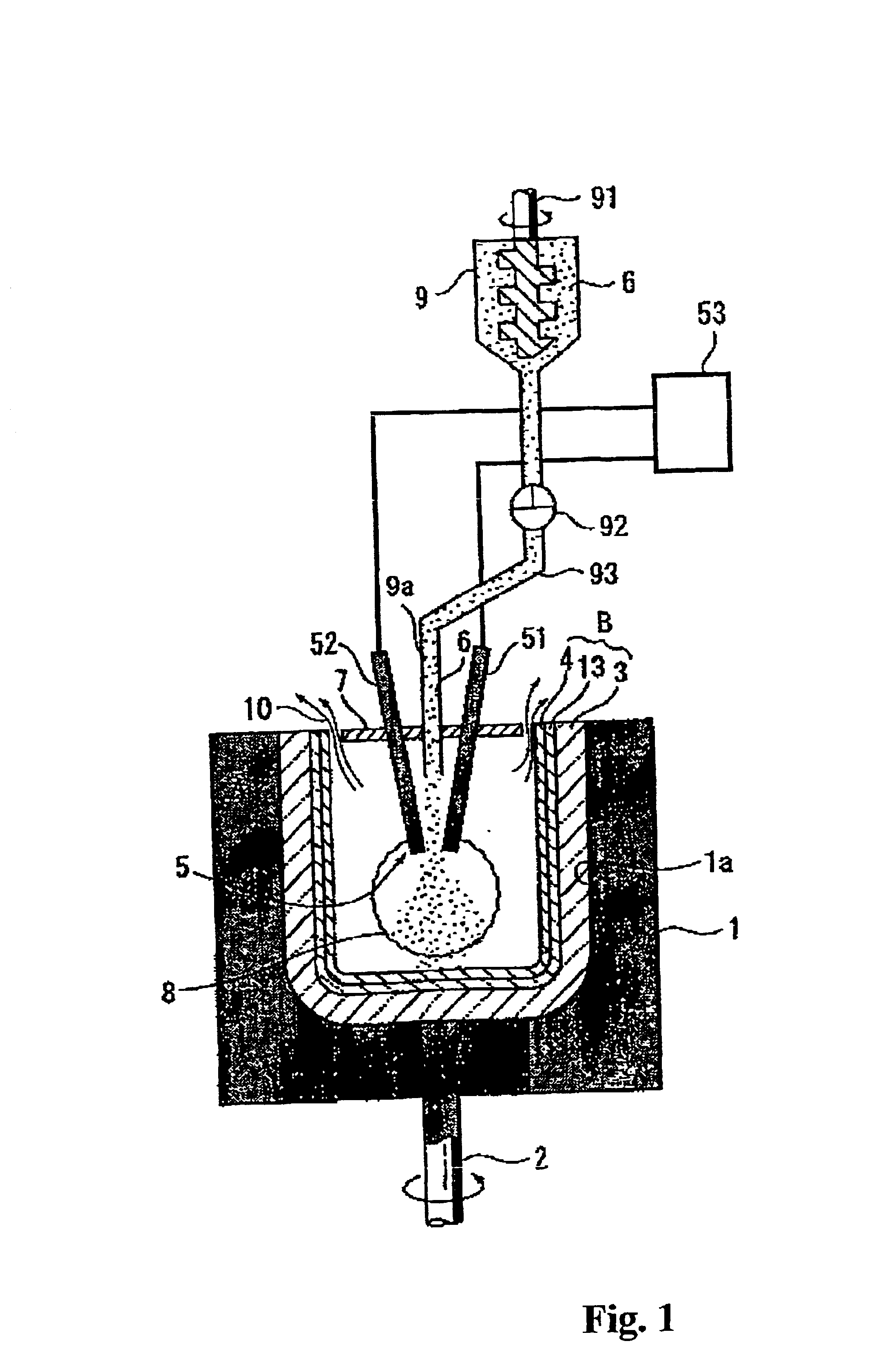
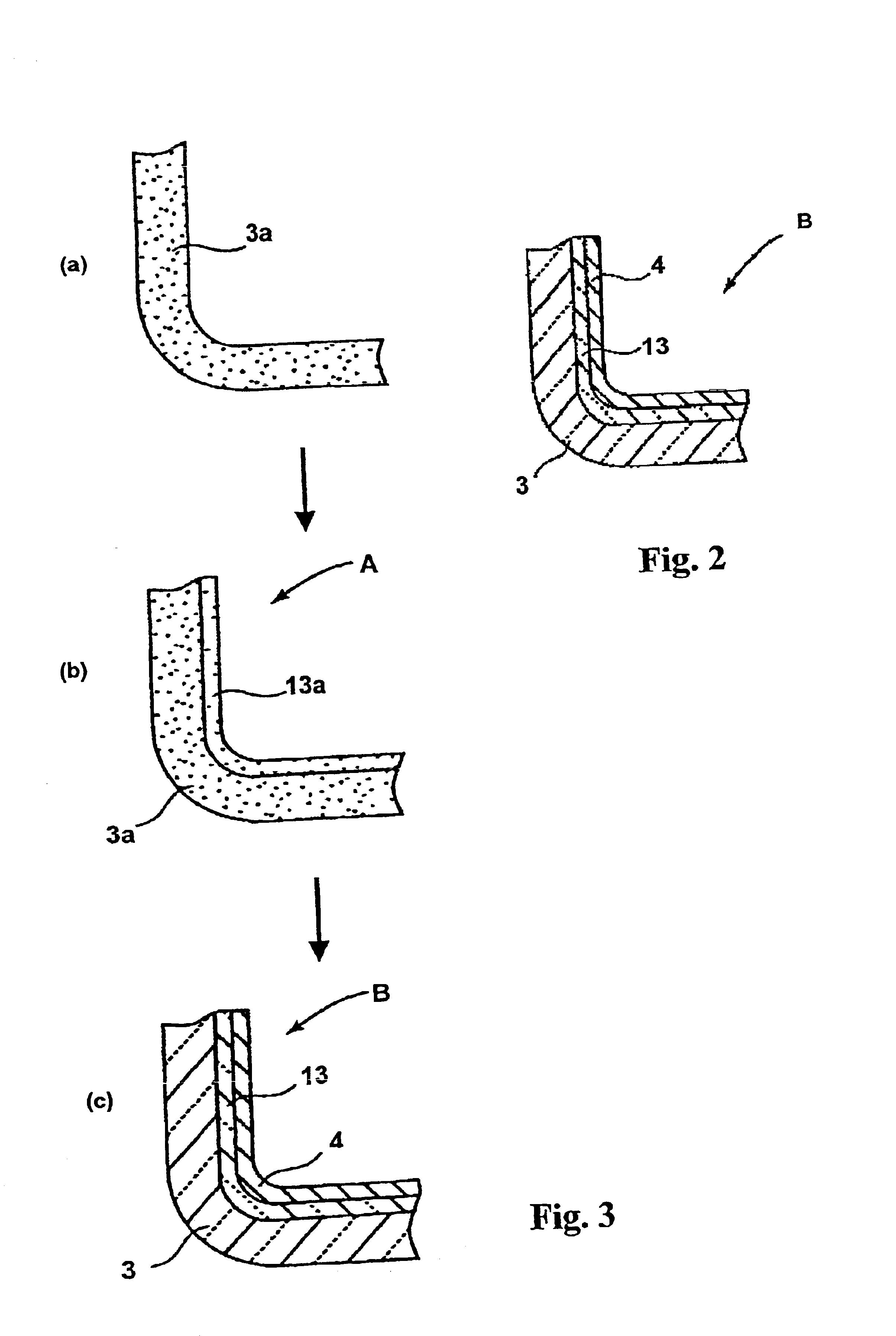
Referring to FIGS. 1, 2, and 3, the process for producing a multilayer structured quartz glass crucible according to a first embodiment of the method for producing a quartz glass crucible of the present invention is explained below.

Referring to FIG. 1, a rotatable mold 1 is equipped with a rotating shaft 2, and a cavity 1a is formed in the mold 1. Firstly, an outer layer molded body 3a in a crucible shape having a desired thickness is molded by supplying a naturally occurring quartz powder inside the cavity 1a provided to the rotating mold 1, and by applying centrifugal force thereto. Subsequently, a synthetic quartz glass powder is supplied to the inner side of the resulting outer layer molded body 3a made of a naturally occurring quartz powder to obtain an intermediate molded body 13a made of the synthetic quartz glass powder layer formed at a desired thickness along the inner side of the outer layer molded body 3a. Then, thus obtained double layered molded body A is heated and fu...

second embodiment

Then, by making reference to FIGS. 1, 2, and 4, the process for producing a multilayer structured quartz glass crucible according to a second embodiment of the method for producing a quartz glass crucible of the present invention is explained below.

Firstly, an outer layer molded body 3a is molded into a shape of a crucible by supplying a naturally occurring quartz powder inside the cavity 1a provided to the rotating mold 1 while applying centrifugal force thereto. Subsequently, after forming an outer layer 3 made of a naturally occurring quartz glass by heating and fusing from the inner side, a synthetic quartz glass powder is supplied to the inner side of the resulting outer layer 3 to obtain an intermediate molded body 13a made of synthetic quartz glass powder at a desired thickness. Then, while heating and fusing the intermediate layer molded body 13a from the inner side by using arc discharge, a synthetic quartz glass powder 6 is supplied to the high temperature gaseous atmosphe...

example 1

By using the apparatus shown in FIG. 1 and in accordance with the method illustrated in FIG. 3, a naturally occurring quartz powder was supplied inside a rotating mold to obtain an outer layer molded body comprising a powder layer 30 mm in thickness, and a synthetic quartz glass powder was subsequently supplied thereto to form an intermediate layer molded body 1.5 mm in thickness comprising the synthetic quartz glass powder provided along the inner side of the outer layer molded body. Thus was obtained a molded body having a double layer structure.

Then, at the same time with heating and fusing the double layered structured molded body from the inner side by means of arc discharge, a synthetic quartz glass powder, as a material for forming the transparent layer, was newly supplied into the high temperature gaseous atmosphere at a rate of 100 g / min to obtain a three-layer structured quartz glass crucible 22 inch in diameter. The thus obtained three-layer structured quartz glass crucib...


PUM

PropertyMeasurementUnit
total thicknessaaaaaaaaaa
thicknessaaaaaaaaaa

Abstract

Disclosed is a multilayer structured quartz glass crucible, for pulling up silicon single crystal, whose structure has at least three layers comprising: a translucent outer layer made of naturally occurring quartz glass and having a large number of pores, a translucent intermediate layer, made of synthetic quartz glass and having a large number of pores, and a transparent inner layer substantially free from pores and made of a synthetic quartz glass. Thermal convection within the silicon melt is suppressed by use of the quartz glass crucible, thereby preventing oscillation on the surface of the silicon melt. A method for producing the quartz glas crucible is also disclosed.

Description

TECHNICAL FIELD TO WHICH THE INVENTION BELONGSThe present invention relates to a multilayer structure quartz glass crucible favorably used in pulling up single crystal silicon for use in the production of semiconductors, and to a method for producing said quartz glass crucible.RELATED ARTIn the production of a single crystal silicon in accordance with the Czochralski (CZ) process, commonly used heretofore is a quartz glass crucible as a vessel for placing therein a silicon melt. Generally, the quartz glass crucible is produced by molding it inside a mold by using a quartz powder produced by crushing and purifying a naturally occurring (crystalline) quartz, followed by fusing it by arc heating. The quartz glass crucible produced in accordance with the method above is obtained by supplying a powder of quartz raw material inside a rotating mold, then depositing it on the inner wall of the mold by taking advantage of the centrifugal force to form a mold body in the shape of the crucible...

Claims


Application Information

Patent Timeline
Patent Type & Authority Patents(United States)
IPC IPC(8): C03B19/09C03B19/00C30B15/10C30B35/00C03B20/00
CPCC03B19/095C30B15/10C30B35/002Y10T117/1024Y10T117/1016Y10T428/13Y10T117/10Y10T428/131Y10T428/1317Y02P40/57
Inventor OHAMA, YASUOMATSUI, HIROSHI
Owner HERAEUS QUARZGLAS
Learn More