Piezoelectric resonator apparatus with acoustic reflector

a resonator and acoustic technology, applied in the field of resonator apparatus, can solve the problems of difficult further processing, difficult to realize the above-mentioned layer thickness, and difficult to process,

Inactive Publication Date: 2005-01-11
AVAGO TECH INT SALES PTE LTD
View PDF4 Cites 95 Cited by
  • Summary
  • Abstract
  • Description
  • Claims
  • Application Information

AI Technical Summary

Benefits of technology

It is the object of the present invention to provide an improved resonator apparatus in which the above-stated problems associated with the m

Problems solved by technology

The disadvantage of this procedure is that the resulting structure is very sensitive and difficult to process further, in particular with regard to the packaging of such a structure.
First, the realization of the above-mentioned layer thicknesses dopt may be problematic for technological reasons.
This problem occurs in metals such as tungsten, platinum or molybdenum.
Metal layers with such thicknesses can be realized technologically only with difficulty.
Another problem is the parasitic capacitances in the device towards the substrate.
Anothe

Method used


Image

  • Piezoelectric resonator apparatus with acoustic reflector
  • Piezoelectric resonator apparatus with acoustic reflector
  • Piezoelectric resonator apparatus with acoustic reflector

Examples


Embodiment Construction

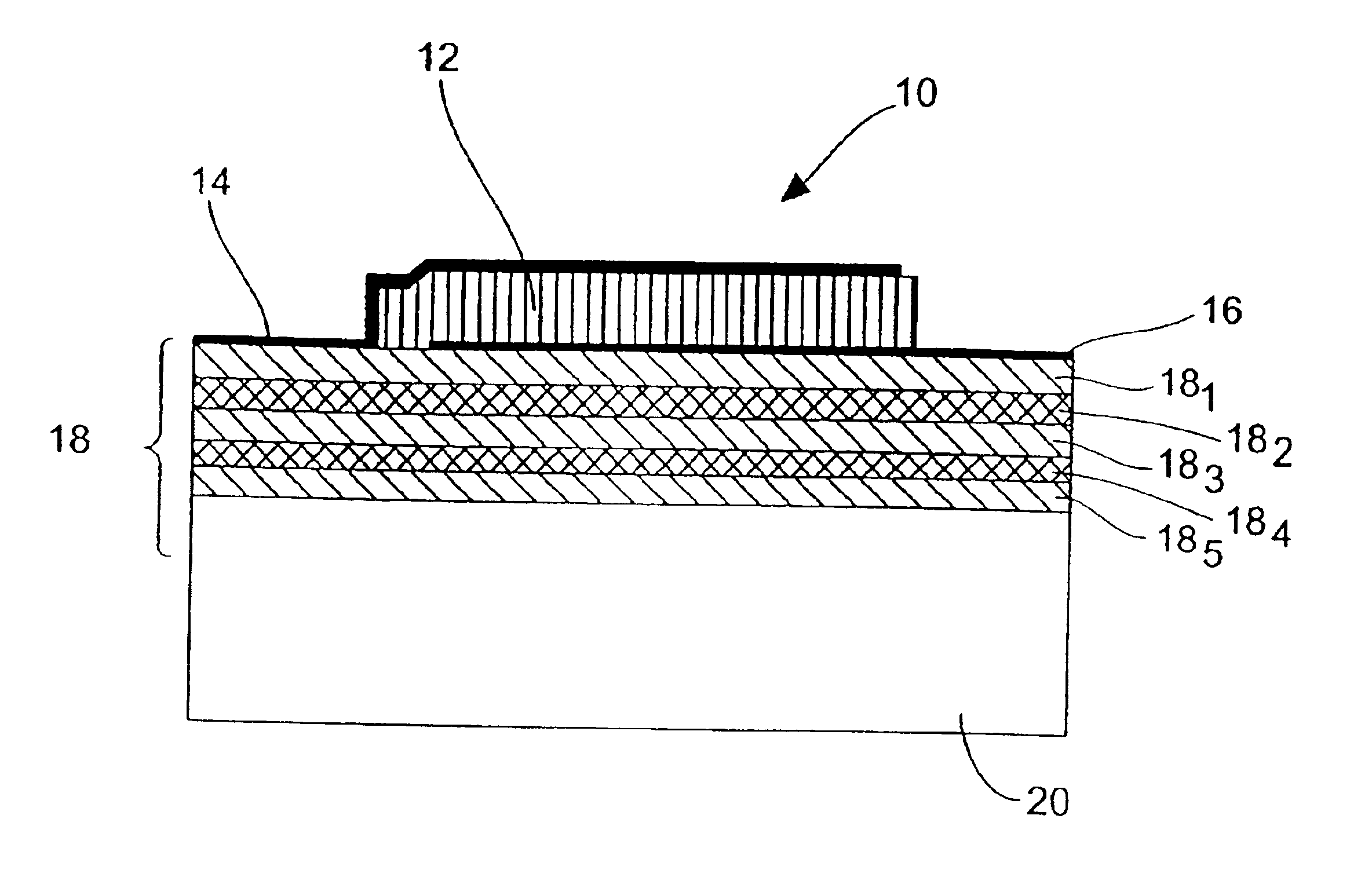
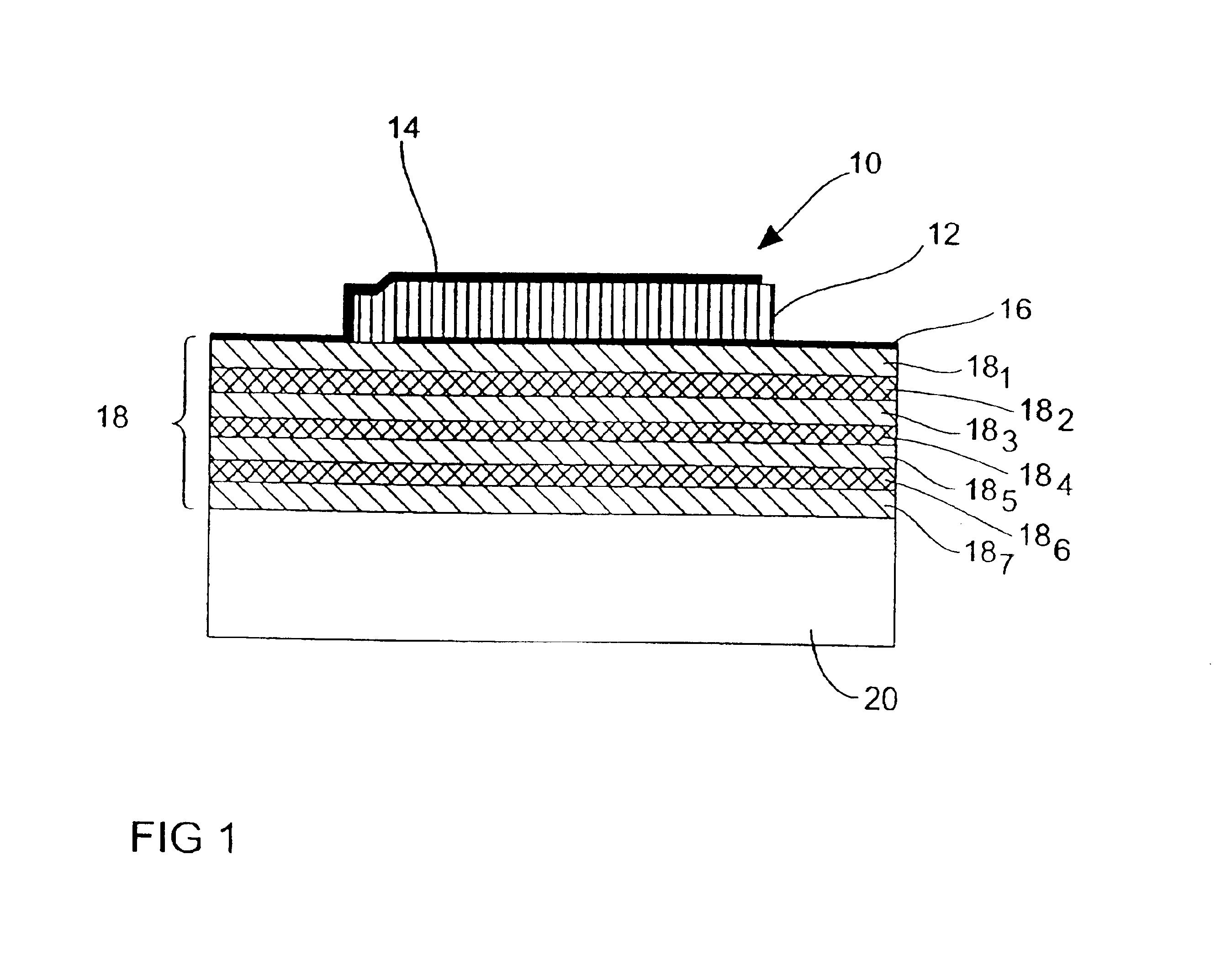
With the help of FIG. 2 a preferred embodiment of the present invention is explained in greater detail below. The representation of the resonator apparatus in FIG. 2 is similar to th at in FIG. 1, but according to the embodiment the reflector 18 comprises only five layers 181 to 185, which furthermore depart from the embodiment illustrated in FIG. 1 in that their thicknesses depart from the optimum thicknesses of the layers as they are determined for these optimum layer thicknesses according to the above stated condition (1).

In FIG. 2 an embodiment is shown in which the Bragg reflector 18 comprises a succession of layers consisting of a SiO2-layer 181, a Mo-layer 182, a SiO2-layer 183, a Mo-layer 184 and a SiO2-layer 185. The resonance frequency of the resonator apparatus is 900 MHz. For the further consideration it is assumed that, without limiting the general character, silicon is the substrate material and 12 ZnO is the piezoelectric material.

If the above condition with regard to...


PUM


Abstract

A resonator apparatus has a piezoelectric resonator as well as an acoustic reflector which has a layer having a high acoustic impedance and a layer having a low acoustic impedance. The thickness of one layer is set different from a quarter of the wavelength in this layer at the operating frequency due to technological limitations in the manufacturing of this layer, and the thickness of the other layer is set dependent from the one layer, such that a predetermined minimum quality of the acoustic reflector is attained.

Description

BACKGROUND OF THE INVENTION1. Field of the InventionThe present invention relates to a resonator apparatus, in particular to a resonator apparatus having a piezoelectric resonator and an associated acoustic reflector.2. Description of the Related ArtIn FIG. 1 a resonator apparatus comprising a piezoelectric resonator 10 is shown by way of example. The piezoelectric resonator 10 comprises a piezoelectric layer 12 as well as a first electrode 14 and a second electrode 16. An acoustic Bragg reflector 18 comprising a plurality of layers 181 to 187 is arranged adjacent to the piezoelectric resonator 10. Further, a substrate 20 is provided. The reflector 18 is arranged between the substrate 20 and the piezoelectric resonator 10. The layers 181, 183, 185 and 187 of the acoustic reflector are layers having a low acoustic impedance, and the layers 182, 184, and 186 are layers having a high acoustic impedance.In piezoelectric thin film resonators (TFBAR=thin film bulk acoustic wave resonator,...

Claims


Application Information

Patent Timeline
IPC IPC(8): H03H9/17H03H9/00H01L41/187H03H9/02H01L41/09
CPCH03H9/175H03H9/02125H03H9/17
Inventor AIGNER, ROBERTELBRECHT, LUEDERMARKSTEINER, STEPHANTIMME, HANS-JOERG
Owner AVAGO TECH INT SALES PTE LTD
Why Eureka
Try Eureka