
Control for two or more dc motors, in particular actuators for adjustment of furniture

a dynamo-electric motor and control technology, applied in the direction speed regulation of multiple dynamo-electric motors, rigid tables, etc., can solve the problems of relatively high cost and complicated control technology, and achieve the effect of low cos

Inactive Publication Date: 2005-01-11
LINAK AS
View PDF23 Cites 23 Cited by
  • Summary
  • Abstract
  • Description
  • Claims
  • Application Information

AI Technical Summary

Benefits of technology

The object of the invention is to provide a simple and low cost control which may be used for operating two or more actuators to obtain uniform travel thereamong.
It will be appreciated that the control departs from the previously mentioned controls in that the actuator does not have to travel a distance before an adjustment can take place, but that, instead, the energy transformed in the motor is used as the basis, thus allowing a quicker adjustment to be made.
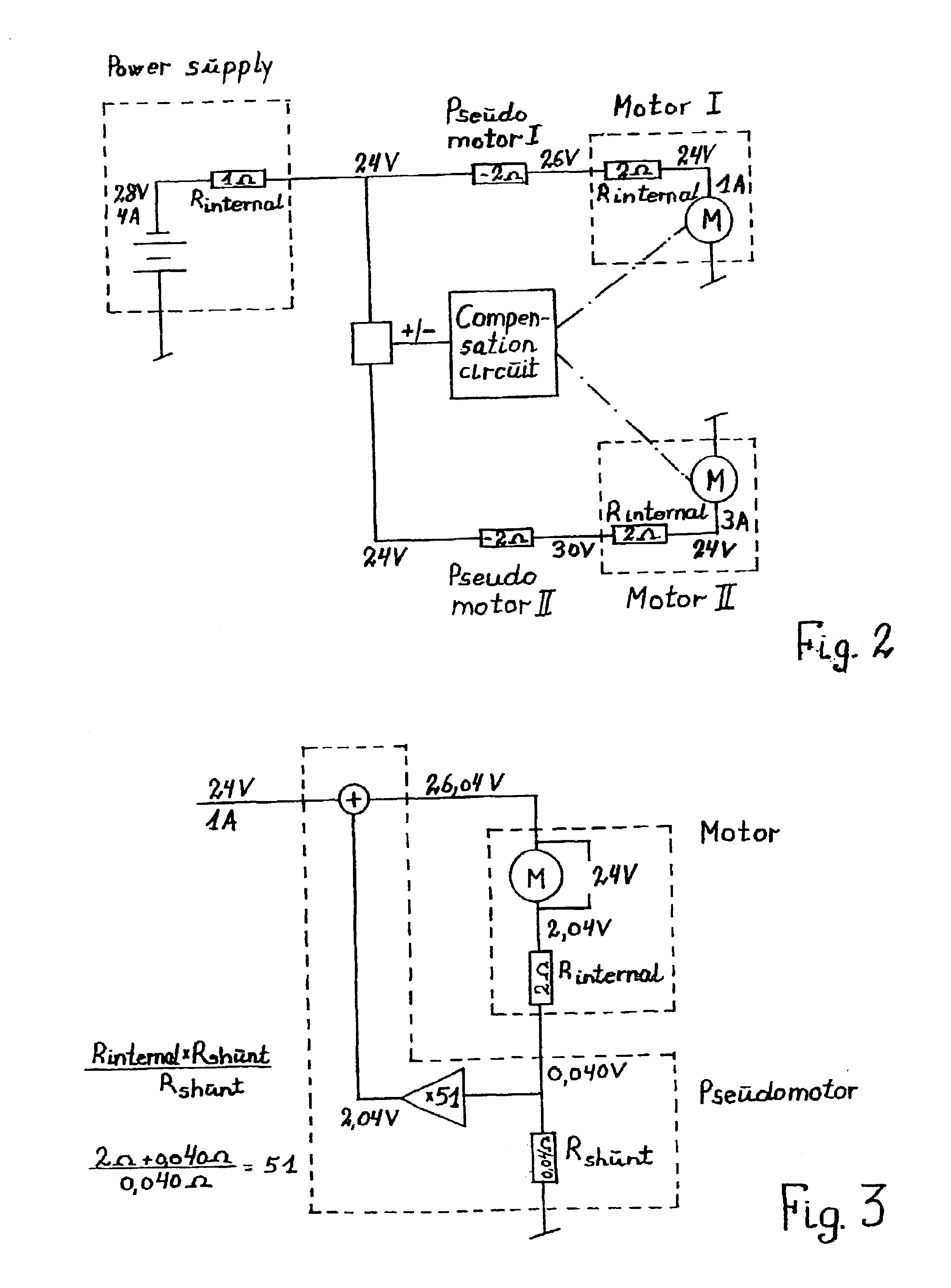
It is recognized that there is a certain deviation in the electrical values of the motors, which results in inaccuracy in the control. This is obviated in that the present control additionally comprises a compensation circuit based on the frequency of the commutator noise from the individual motors, wherein a comparison is made in the compensation circuit of the frequencies from the individual motors, and in case of a deviation of the frequency from one motor relative to the frequencies of the others, the power supply to said motor or to the other motors is adjusted so that the frequencies correspond. This results in a very accurate control of the motors.
The present control may be implemented at low cost and without computer control. It will be appreciated that this does not rule out the possibility that the invention may be used in general for the control of two or more DC motors.

Problems solved by technology

These controls are relatively expensive and complicated since they are based on computer controls.

Method used


Image

  • Control for two or more dc motors, in particular actuators for adjustment of furniture
  • Control for two or more dc motors, in particular actuators for adjustment of furniture
  • Control for two or more dc motors, in particular actuators for adjustment of furniture

Examples


Embodiment Construction

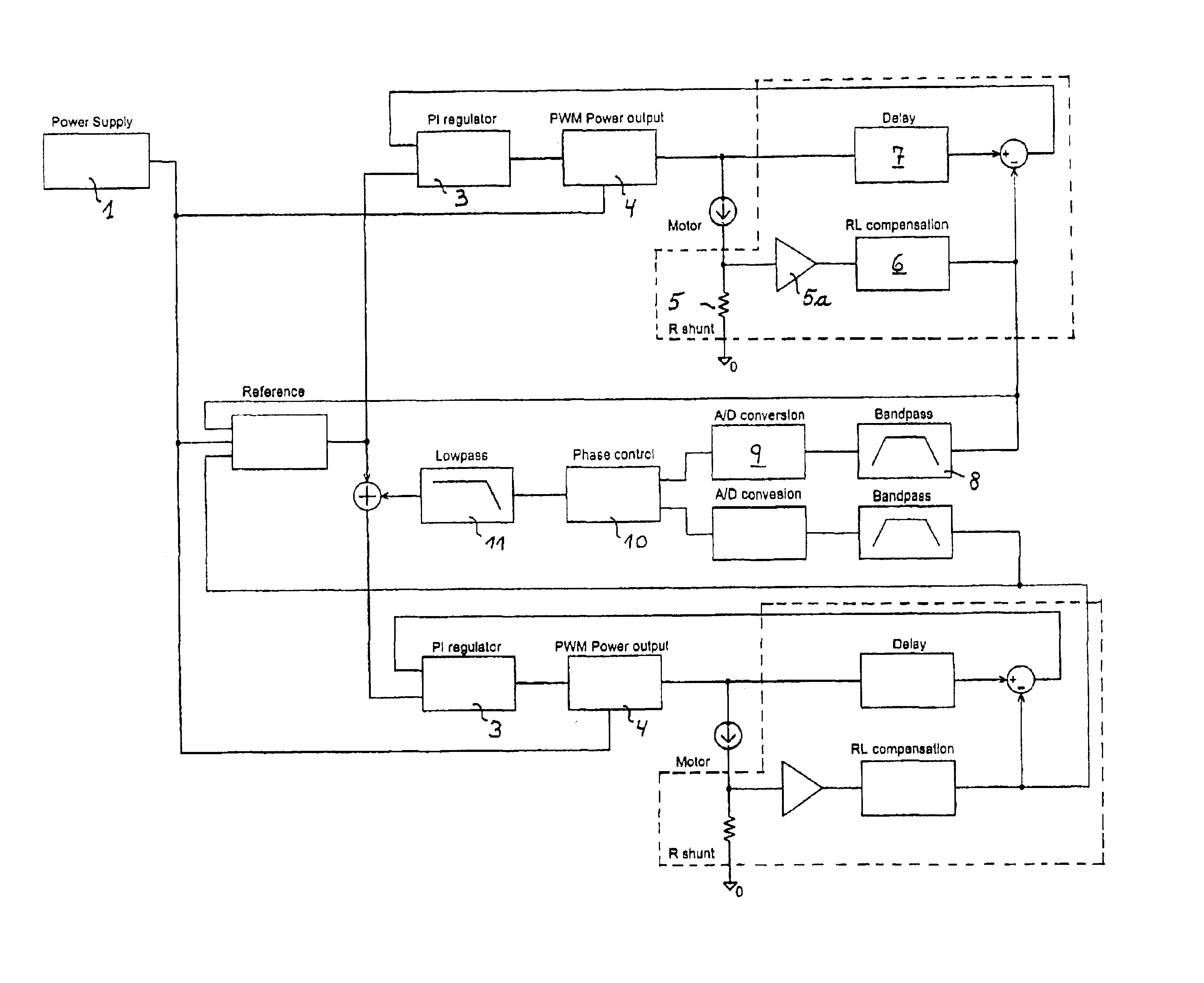
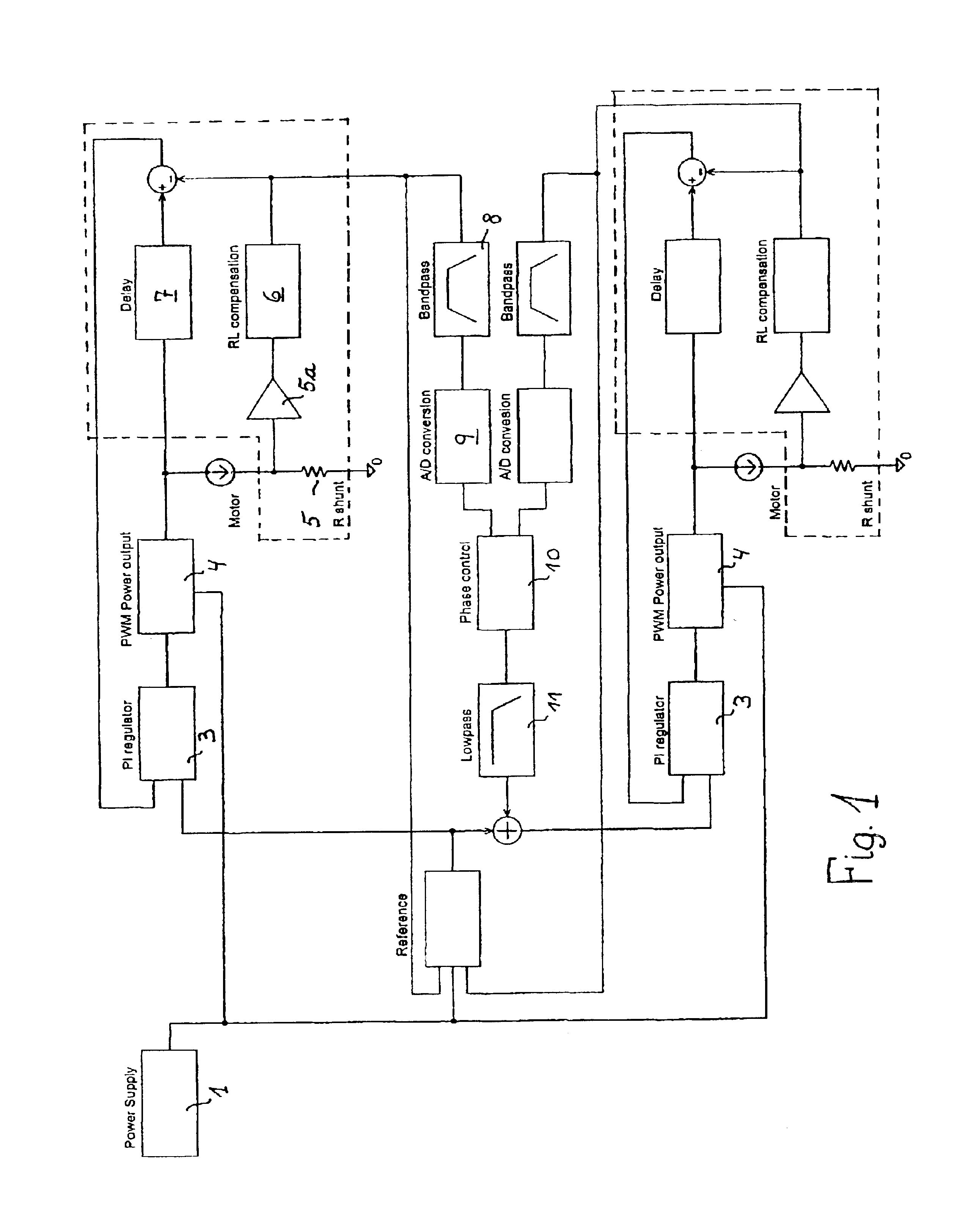
Referring now to the block diagram in FIG. 1 the present control comprises:

1:A power supply2:A reference3:A PI regulator4:A PWM power output5:A R shunt with amplifier6:A RL compensation7:A delay8:A band-pass filter9:A A / D conversion10:A phase control11:A low-pass filter

1: Power Supply

The power supply comprises a transformer, a bridge coupling and a rectifier capacitor. It supplies the necessary energy to the system and is therefore the “block” that limits the performance of the system with respect to load and speed of the actuators. The voltage is unregulated, therefore is superposed by some ripple when loaded.

2: Reference

The reference “block” controls the system, and determines how fast the actuators must / may run. The reference circuit receives information from the two actuators and the power supply, and supplies a reference voltage based on the information that enables the other circuits to stay within their regulation ranges.

3: PI Regulator

The PI regulator regulates the speed of ...


PUM


Abstract

A control for DC motors, in particular actuators driven by a DC motor for adjustment of furniture, such as tables, beds, chairs, etc. includes a pseudomotor which is capable of supplying a voltage that corresponds to the motor speed on the basis of the current and voltage supplied to the motor. The voltage of the pseudomotor is supplied to an adjustable power supply, where it is compared with an internal reference voltage and adjusts the voltage difference down to the smallest possible difference between the voltage of the pseudomotor and the internal reference voltage. For greater accuracy, the control additionally includes a compensation circuit configured to evaluate a dominating frequency in the commutator noise. Thus, there is provided a simple and low cost control for parallel running of two or more actuators.

Description

BACKGROUND OF THE INVENTIONThe present invention relates to a control for two or more DC motors, in particular actuators driven by a DC motor for adjustment of furniture, such as tables, beds, chairs, etc, wherein the motors are connected to an adjustable power supply, and wherein the control is adapted to adjust the power supply to the individual motors such that the motors mutually keep the same or essentially the same speed independent of different loads on them.Adjustment of beds and tables is performed using linear actuators of the type which comprises a spindle driven by a reversible DC motor, said spindle being provided with a spindle nut which, either directly or via an extension rod, is connected with the element to be adjusted. For a height-adjustable desk carried by a single leg at each side there is a linear actuator in each leg, and for beds there is one at each end for lifting the mattress frame. U.S. Pat. No. 5,224,429 Haworth Inc. describes such a height adjustable d...

Claims


Application Information

Patent Timeline
IPC IPC(8): H02P5/50H02P5/46A61G7/018A61G7/002
CPCH02P5/50A61G7/018
Inventor BASTHOLM, JEPPE
Owner LINAK AS
Learn More