Battery cell balancing system

a battery and cell voltage technology, applied in the field of battery cell voltage balancing system, can solve the problems of complex protection circuit, adversely affecting the reliability of the battery system and ultimately the spacecraft itself, and the above-stated approach is complex and costly, so as to increase the reliability and life of the battery

Inactive Publication Date: 2005-01-18
THE BOEING CO
View PDF4 Cites 48 Cited by
  • Summary
  • Abstract
  • Description
  • Claims
  • Application Information

AI Technical Summary

Benefits of technology

Another advantage of the present invention is that control of the preferential charging is performed by self-contained random logic through statistical selection of the cells to be balanced, which increases reliability and life of the battery over prior battery balancing systems. The present invention associates the cells into subgroups, each cell may be a member of multiple subgroups, and randomly balances each subgroup. Association into subgroups reduces effect a single cell, that is unable to charge, may have on charging of other cells.
The present invention itself, together with further objects and attendant advantages, will be best understood by reference to the following detailed description, taken in conjunction with the accompanying drawing.

Problems solved by technology

The cells are sensitive to over-charging and over-discharging, thereby requiring complex protection circuits.
The above stated approach is complex and costly, especially for space applications, which are sensitive to weight and packaging constraints.
Increasing number of battery system components adversely affects reliability of a battery system and ultimately a spacecraft itself.
This approach is also complex and costly.
During charge of the cells valuable bus power is wasted when the voltage clamp is protecting the cells from overcharging.
Also, the clamp circuit typically requires additional heat sinking to dissipate heat.
There is a dependency on electro-mechanical devices to protect the cells from over discharging, and such devices have limited life cycles.
Although this method may be cost effective it requires complex control techniques which tax limit control system intelligence.
T he method uses complex computer software and significantly reduces onboard processor resources.
Although, this technique is cost effective it is also complex due to a need for control elements, thus reducing processor resources.
Prior art battery balancing techniques that preferentially charge a cell having a lowest state of charge are also inefficient.
When cell voltage reversal occurs, cell potential inverts and the cell is shorted, also rendering the battery inoperable.

Method used


Image

  • Battery cell balancing system
  • Battery cell balancing system
  • Battery cell balancing system

Examples


Embodiment Construction

While the present invention is described with respect to a method and system for balancing battery cells, the present invention may be adapted for various applications and systems including: aeronautical systems, land-based systems, commercial systems, terrestrial industrial systems, vehicle systems, or other applications or systems known in the art.

In the following description, various operating parameters and components are described for one constructed embodiment. These specific parameters and components are included as examples and are not meant to be limiting.

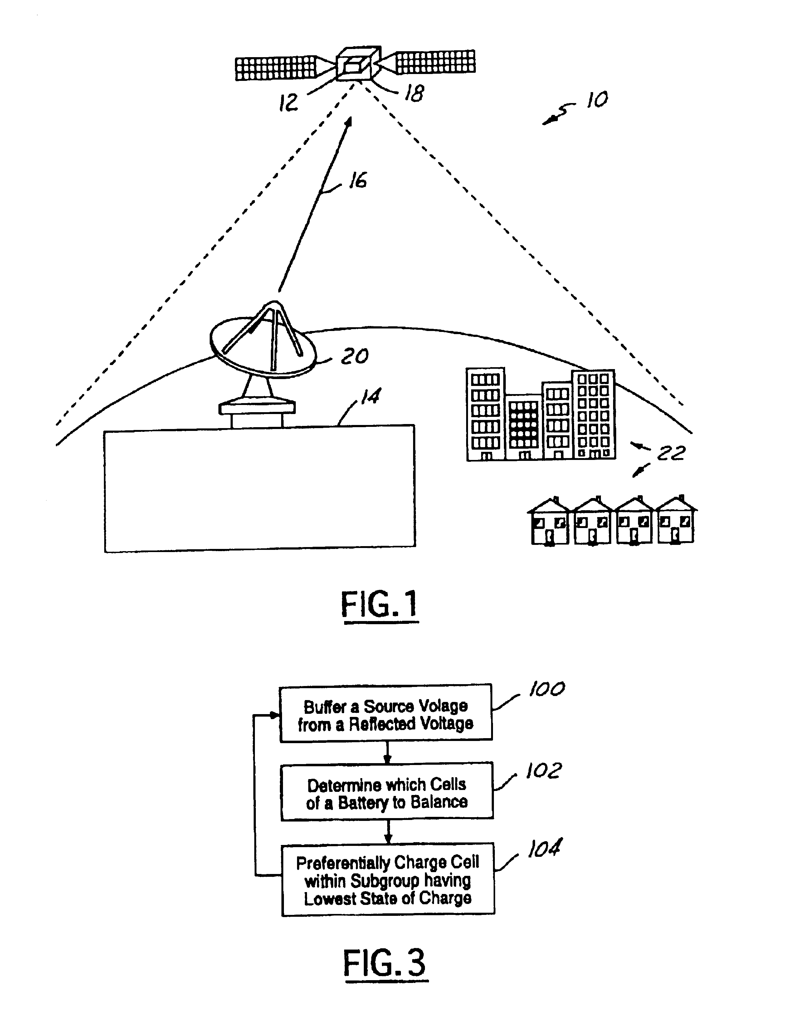
Referring now to FIG. 1, a perspective view of a satellite system 10 utilizing a battery balancing system 12 in accordance with an embodiment of the present invention is shown. The system 10 includes a ground station 14 for transmitting communication signals 16 over various channels to a satellite 18 via a transceiver 20. The satellite 18 then retransmits the communication signals to multiple sites 22. The sites 22 may inc...


PUM


Abstract

A battery cell balancing system (12) for a battery (30) having a plurality of cells (32) is provided. The system (12) includes a power supply (38) and a plurality of transformer/rectifier circuits (34) electrically coupled to the cells (32). Preferential charging occurs for a cell with the lowest state of charge. At least one current limiting device (36) is electrically coupled to the transformer/rectifier circuits (34) and the power supply (38). The current limiting device (36) buffers a source voltage from a reflected voltage of at least one of the plurality of cells (32). A method of performing the same is also provided.

Description

TECHNICAL FIELDThe present invention relates generally to aeronautical vehicle systems, and more particularly, to a method and system for balancing cell voltage of a battery.BACKGROUND OF THE INVENTIONA spacecraft may have several lithium-ion batteries, each of which having approximately thirty cells. The cells are sensitive to over-charging and over-discharging, thereby requiring complex protection circuits.A common approach for charging the batteries and balancing charge of each cell includes the use of a power supply for each cell, totaling approximately 120 power supplies. As known in the art, it is desirable to minimize the number spacecraft system components and weight of the spacecraft. The above stated approach is complex and costly, especially for space applications, which are sensitive to weight and packaging constraints.It is also desirable in space applications for systems to be reliable. Increasing number of battery system components adversely affects reliability of a b...

Claims


Application Information

Patent Timeline
Patent Type & Authority Patents(United States)
IPC IPC(8): B64G1/42H02J7/00H02J7/02
CPCB64G1/425H02J7/0018B64G1/428
Inventor CANTER, STANLEY
Owner THE BOEING CO
Why Eureka
Try Eureka