Photonic band gap fiber

a fiber and band gap technology, applied in semiconductor lasers, instruments, manufacturing tools, etc., can solve the problems of insufficient pbg of the structure described by birks et al., the dimensions of the features forming the triangular periodic structure must be very large, and the core of the fibre cannot be formed. to achieve the effect of increasing the refractive index of the core region

Inactive Publication Date: 2005-01-18
CRYSTAL FIBRE AS
View PDF10 Cites 118 Cited by
  • Summary
  • Abstract
  • Description
  • Claims
  • Application Information

AI Technical Summary

Benefits of technology

In this situation, further low index areas may be provided. When positioned correctly, these will separate the high index areas in that the coupling via the bridges is reduced due to the bridges being narrowed in effective area or width even when increased in number.
Also, the dopant may comprise a photosensitive material, such as germanium or deuterium, in order to facilitate e.g. the wilting of gratings in the fibre or core region or for increasing the refractive index of the core region.

Problems solved by technology

It may be a problem or disadvantage of this particular realisation of optical fibres with periodic dielectric cladding regions that careful stacking of either hexagonal glass tubes (with central holes) or direct stacking of thin circular tubes is required.
Although these fibres according to the reports in the international literature show quite specific and new optical properties, one of the problems has been that the core of the fibre could only be formed by introduction of a glass rod without a central hole.
It is a further disadvantage that even these new fibres have core areas with higher refractive index than the average refractive index of the surrounding media, and their waveguiding effect may, consequently, also be described by conventional total internal reflection.
It is a still further disadvantage that, due to the triangular cladding structure, the PBG of the structures described by Birks et al. are not optimised for guiding electromagnetic radiation using the PBG effect.
It is a disadvantage of the micro-fabricated optical fibre disclosed in U.S. Pat. No. 5,802,236 that due to the high-index core region the waveguiding characteristics are based on traditional total internal reflection of the electromagnetic radiation guided in the core region.
It is a disadvantage that the triangular cladding structure disclosed in WO 99 / 00685 will not, using realistic manufacturing parameters, provide a sufficient PBG so as to effectively confine visible or NIR electromagnetic radiation within the core region of the fibre.
It is a further disadvantage of the structure disclosed in WO 99 / 00685 that in order to obtain a sufficient PBG, the dimensions of the features forming the triangular periodic structure must be very large.
Such large features, e.g. air-filled holes, make the structure difficult to manufacture and inconvenient for practical applications.

Method used


Image

  • Photonic band gap fiber
  • Photonic band gap fiber
  • Photonic band gap fiber

Examples


Embodiment Construction

Many different realisations of periodic cladding structures exist for low-index-core PBG waveguides, because they ran consist of a void, hole, or any suitable (additional or missing) material(s) disposed periodically in a (first material) matrix. By low-index-core PBG waveguide is meant any structure capable of the guiding electromagnetic fields according to the present invention, such as optical fibres, optical fibre amplifiers, fibre lasers and optical fibre based sensors. Another group of PBG waveguides comprises planar waveguide structures, such as sensors, splitters, couplers, multiplexers, amplifiers and lasers.

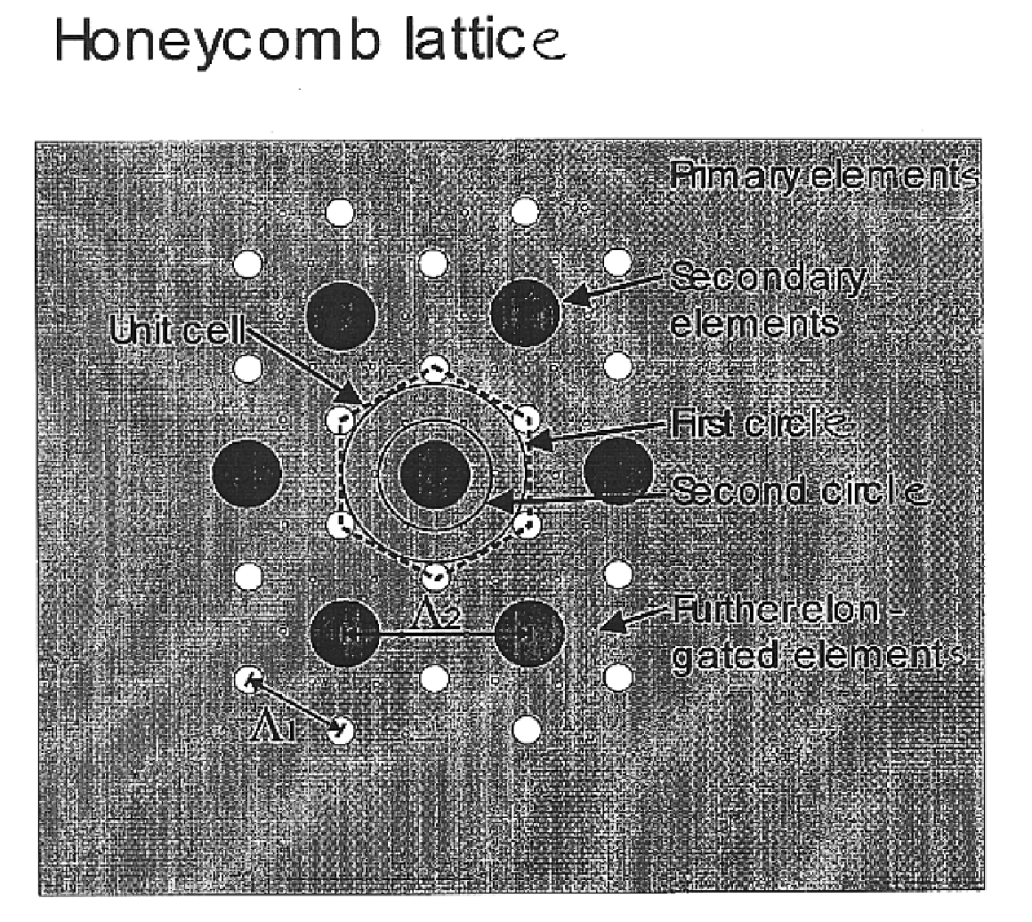
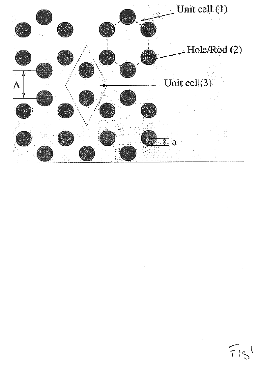
An example of such a periodic micro structured cladding shown in FIG. 16, where additional voids (20) have been centred on a straight line between the original voids (21) forming the 2-dimensional hexagonal (Honeycomb) structure. The function of the additional voids is to modify the penetration of the electromagnetic field between the different unit cells (low-refractiv...


PUM

PropertyMeasurementUnit
diameteraaaaaaaaaa
refractive indexaaaaaaaaaa
areaaaaaaaaaaa

Abstract

An optical fiber having a periodical cladding structure providing an photonic band gap structure with superior qualities. The periodical structure being one wherein high index areas are defined and wherein these are separated using a number of methods. One such method is the introduction of additional low index elements, another method is providing elongated elements deformed in relation to a circular cross section. Also described is a cladding structure comprising elongated elements of a material having an index of refraction higher than that of the material adjacent thereto. Using this additional material, prior art structures may obtain much better qualities.

Description

FIELD OF INVENTIONThe present invention relates to a novel group of cladding designs, especially for use in optical fibres, wherein a larger photonic band gap may be provided while retaining the stability and physical properties of the fibre.BACKGROUND OF THE INVENTIONOptical fibres and integrated optical waveguides are today applied in a wide range of applications within areas such as optical communications, sensor technology, spectroscopy, and medicine. These waveguides normally operate by guiding the electromagnetic field (the light or the photons) through a physical effect, which is known as total internal reflection. By using this fundamental effect, the propagation (or loss) of optical power in directions perpendicular to the waveguide axis is reduced.In order to obtain total internal reflection in these waveguides, which are often fabricated from dielectric materials (in optical fibres) or semiconductors (in integrated optics), it is necessary to use a higher refractive index...

Claims


Application Information

Patent Timeline
Patent Type & Authority Patents(United States)
IPC IPC(8): B29D11/00C03B37/02C03B37/012C03B37/027C03B37/075C03B37/028G02B6/032G02B6/10G02B6/02G02B6/122H01S3/06H01S3/067H01S5/00H01S5/10
CPCB29D11/00721C03B37/0122C03B37/02781C03B37/028C03B37/075G01N21/031G02B6/02G02B6/02328G02B6/02338G02B6/02347G02B6/02352G02B6/02357G02B6/02371G02B6/02385G02B6/032G02B6/105G02B6/1225B82Y20/00H01S5/105C03B2203/10C03B2203/14C03B2203/16C03B2203/34C03B2203/42G01N21/39G02B6/0239H01S3/06708H01S3/06716H01S3/06737H01S3/06741H01S3/0675H01S5/11G02B6/02309
Inventor BROENG, JESBARKOU, STIG EIGILBJARKLEV, ANDERS OVERGAARD
Owner CRYSTAL FIBRE AS
Why Eureka
Try Eureka