
Method for operating an internal combustion engine

Inactive Publication Date: 2005-01-25
ALSTOM TECH LTD
View PDF31 Cites 22 Cited by
  • Summary
  • Abstract
  • Description
  • Claims
  • Application Information

AI Technical Summary

Benefits of technology

Accordingly, the invention relates to providing a novel method for operating an engine with internal combustion in which external supply of water can be completely eliminated for enriching the working medium of the engine with moisture.
Overall, natural gas is in any case a very suitable fuel for carrying out the method according to the invention. The high methane content of this fuel means that the partial pressure of the water vapor in the pure combustion product is high, with the result that the working medium can rapidly be laden with moisture, but it is of course also possible for the method to be carried out when using relatively high-molecular hydrocarbons, such as especially diesel oil, although the less favorable HIC ratio means that the loading rate is lower, such that it takes a correspondingly longer time to reach the final steady state.
In a second embodiment, the water mass flow is at least partially introduced into a combustion chamber of the engine in order to reduce the levels of nitrogen oxides.

Problems solved by technology

The high methane content of this fuel means that the partial pressure of the water vapor in the pure combustion product is high, with the result that the working medium can rapidly be laden with moisture, but it is of course also possible for the method to be carried out when using relatively high-molecular hydrocarbons, such as especially diesel oil, although the less favorable HIC ratio means that the loading rate is lower, such that it takes a correspondingly longer time to reach the final steady state.

Method used


Image

  • Method for operating an internal combustion engine
  • Method for operating an internal combustion engine
  • Method for operating an internal combustion engine

Examples


Embodiment Construction

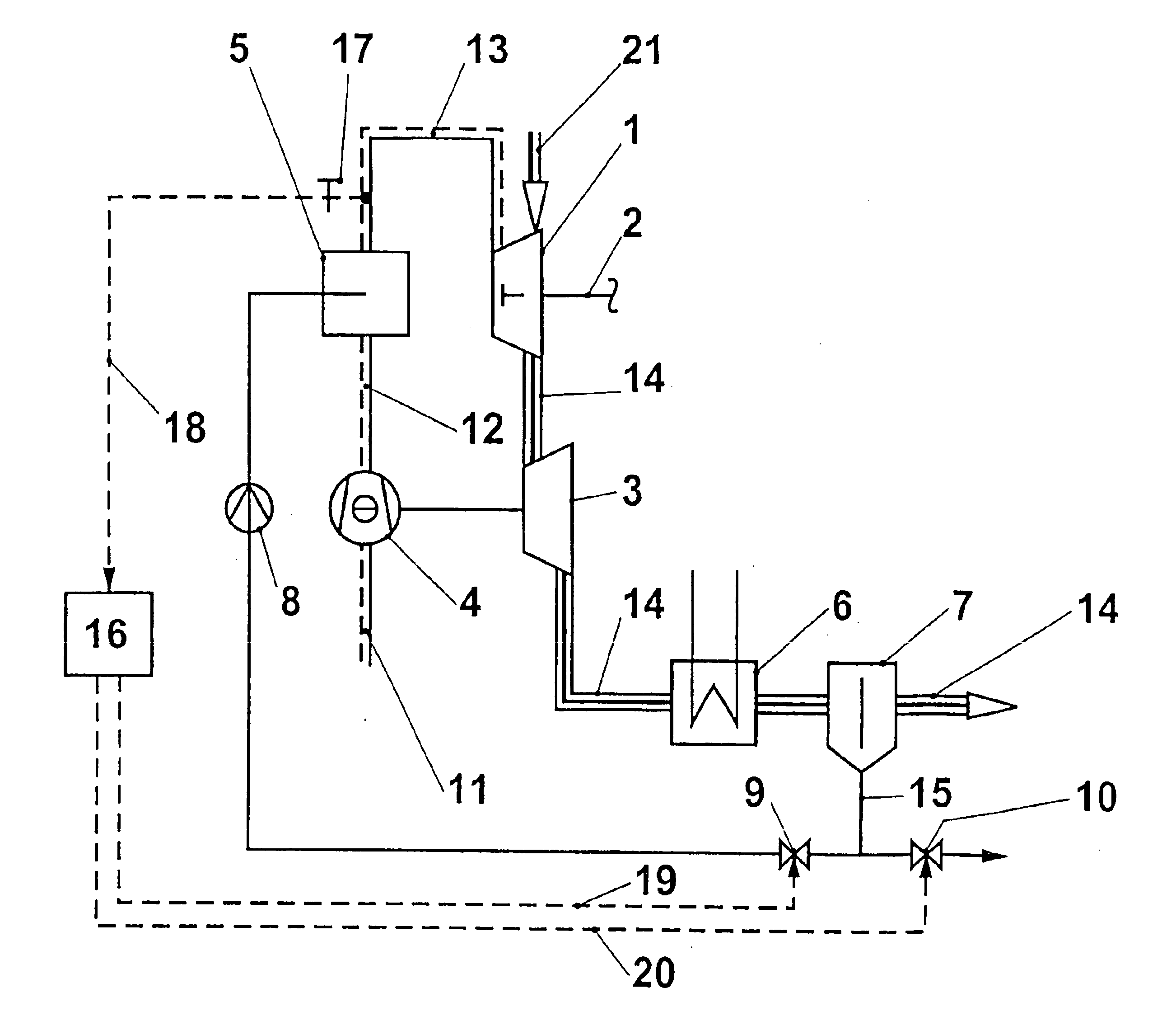
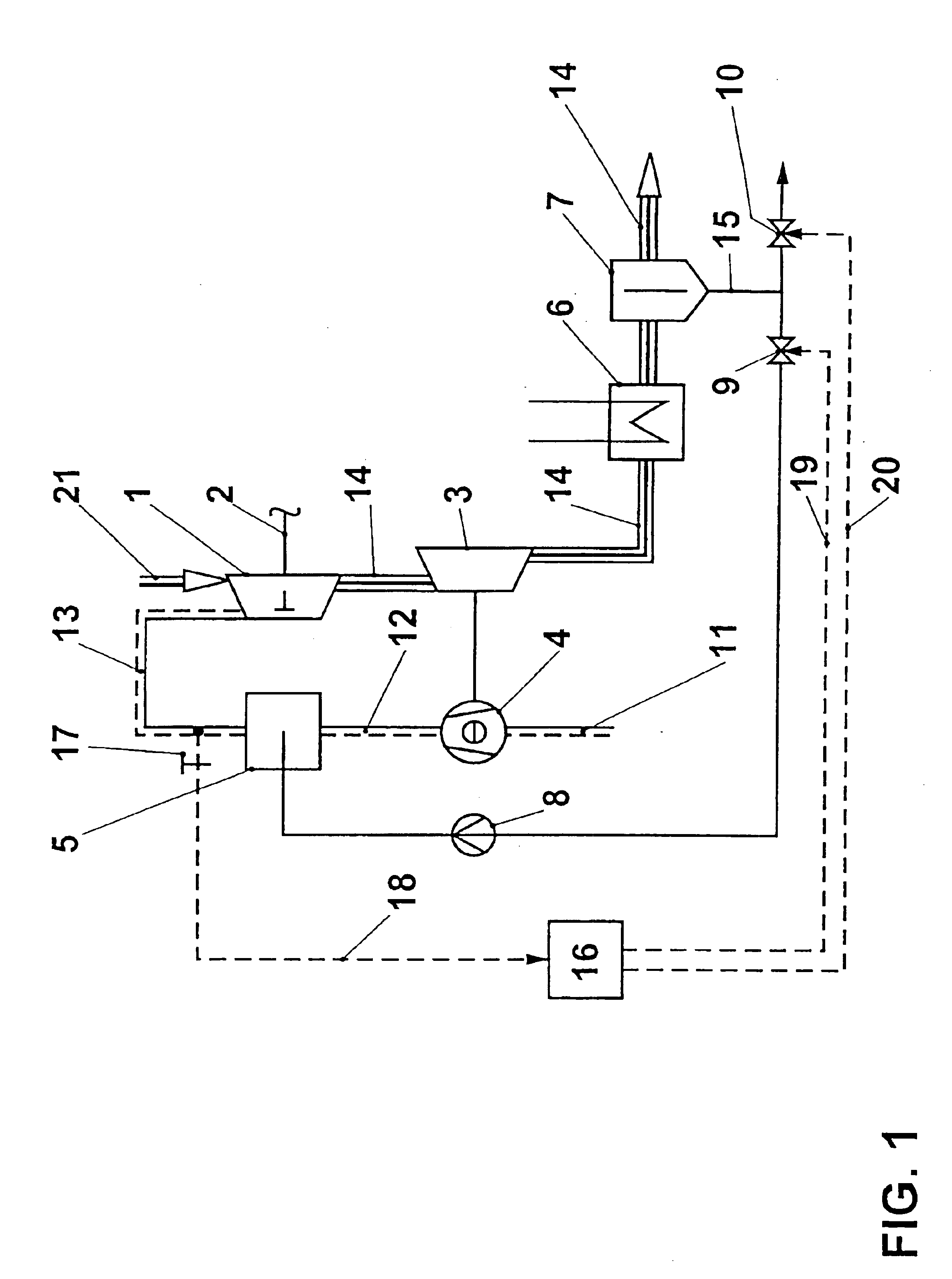
Referring now to the drawings, wherein like reference numerals designate identical or corresponding parts throughout the several views, FIG. 1 shows a diesel engine 1 that is provided with turbocharging and drives a generator, a vehicle or some other power consumer via an output shaft 2. Exhaust gas 14 from the diesel engine flows into the turbine 3 of an exhaust-gas turbocharger. The turbine 3 drives a radial compressor 4. This radial compressor precompresses an intake air stream 11, in such a manner that the cylinders of the diesel engine are filled with a greater quantity of combustion air for a given displacement. During the precompression, the intake air stream is heated, which in turn has adverse effects on the cylinder charging. Therefore, a charge air cooler 5 is provided between the compressor 4 of the exhaust-gas turbocharger and the engine 1. Charge air 12 flows into the charge air cooler 5, where it is cooled, and the engine sucks in cooled charge air 13 with a correspon...


PUM


Abstract

In a turbocharged diesel engine, the charge air is cooled in a charge air cooler designed as an injection intercooler. The water which has been introduced into the working medium of the diesel engine in the charge air cooler, after the working medium has been expanded, is condensed out of the exhaust gas by means of a condenser and a separator and is returned to the charge air cooler. According to the invention, the engine is started without injection of externally supplied water into the charge air cooler. Water which forms during the combustion in the diesel engine is condensed out of the exhaust-gas stream and returned to the charge air cooler. Additional water vapor formed continuously during operation through combustion of diesel fuel is likewise condensed out and introduced into the charge air cooler. In this way, the working medium is laden with moisture until the water mass flow that can be separated out of the exhaust gas is sufficient for the set cooling power of the charge air cooler. Further combustion water that is formed can be used for other purposes. In this way, engines with internal combustion in which water is introduced into the working medium can be operated without an external supply of water.

Description

FIELD OF THE INVENTIONThe invention relates to a method used to enrich the working medium of an internal combustion engine with moisture.BACKGROUND OF THE INVENTIONCharge air cooling is in widespread use in supercharged piston engines, in particular large diesel engines with turbocharging. The cooling of the precompressed combustion air increases the density of the intake working medium and therefore the charge in the cylinders. In the case of coolers which are based on heat exchange with ambient air, cooling water or other cooling media, the dissipation of enthalpy from the cycle process has proven to be disadvantageous. It is known from U.S. Pat. No. 4,440,116 or GB 2 259 326 for water or a water-alcohol mixture to be injected into the working medium upstream or downstream, respectively, of the compressor of a turbocharger. The evaporation extracts heat from the intake air and the overall volume of the working medium decreases. The heat which has been extracted remains present in ...

Claims


Application Information

Patent Timeline
IPC IPC(8): F01K21/00F01K21/04F01N3/00F02B29/04F02B29/00F02C6/12F02C7/143F02C3/30F02C7/12F02C3/20F02C6/00F02B3/06F02B3/00F02B37/00F01N3/02F01N5/02F02M25/022
CPCF01K21/047F02M25/0222F02B29/0481F02B29/0493F02C3/30F02C6/12F02C7/1435F02M25/025F01N3/00F01N2240/22F02B3/06F02B37/00Y02E20/16Y02T10/121Y02T10/146Y02T10/20F05D2260/212Y02T10/12
Inventor FRUTSCHI, HANS ULRICH
Owner ALSTOM TECH LTD
Learn More