Hydraulic transaxle apparatus for a four-wheel driving vehicle and four-wheel driving vehicle using the apparatus

a transaxle and apparatus technology, applied in the direction of electric devices, fluid couplings, gearings, etc., can solve the problems of lack of stability and roadability when working on slopes, vehicle is difficult to bail out, and the power take-off shaft for driving the working device cannot be used as a front wheel drive sha

Inactive Publication Date: 2005-01-25
KANZAKI KOKYUKOKI MFG
View PDF7 Cites 58 Cited by
  • Summary
  • Abstract
  • Description
  • Claims
  • Application Information

AI Technical Summary

Benefits of technology

Due to the above structures, fluid connection of the HST of the first transaxle apparatus to the second hydraulic motor can be ensured without int

Problems solved by technology

However, while the two-wheel-drive vehicle which drives only rear wheels exhibits superior steering performance, it lacks stability when working on a slope and roadability when running on a bad road.
Moreover, the vehicle is difficult to bail out if it becomes stuck, such as in mud, etc.
Therefore, the power take-off shaft for driving the working device cannot be used as a front wheel drive shaft.
Even if another power take-off shaft for front-wheel-drive

Method used


Image

  • Hydraulic transaxle apparatus for a four-wheel driving vehicle and four-wheel driving vehicle using the apparatus
  • Hydraulic transaxle apparatus for a four-wheel driving vehicle and four-wheel driving vehicle using the apparatus
  • Hydraulic transaxle apparatus for a four-wheel driving vehicle and four-wheel driving vehicle using the apparatus

Examples


first embodiment

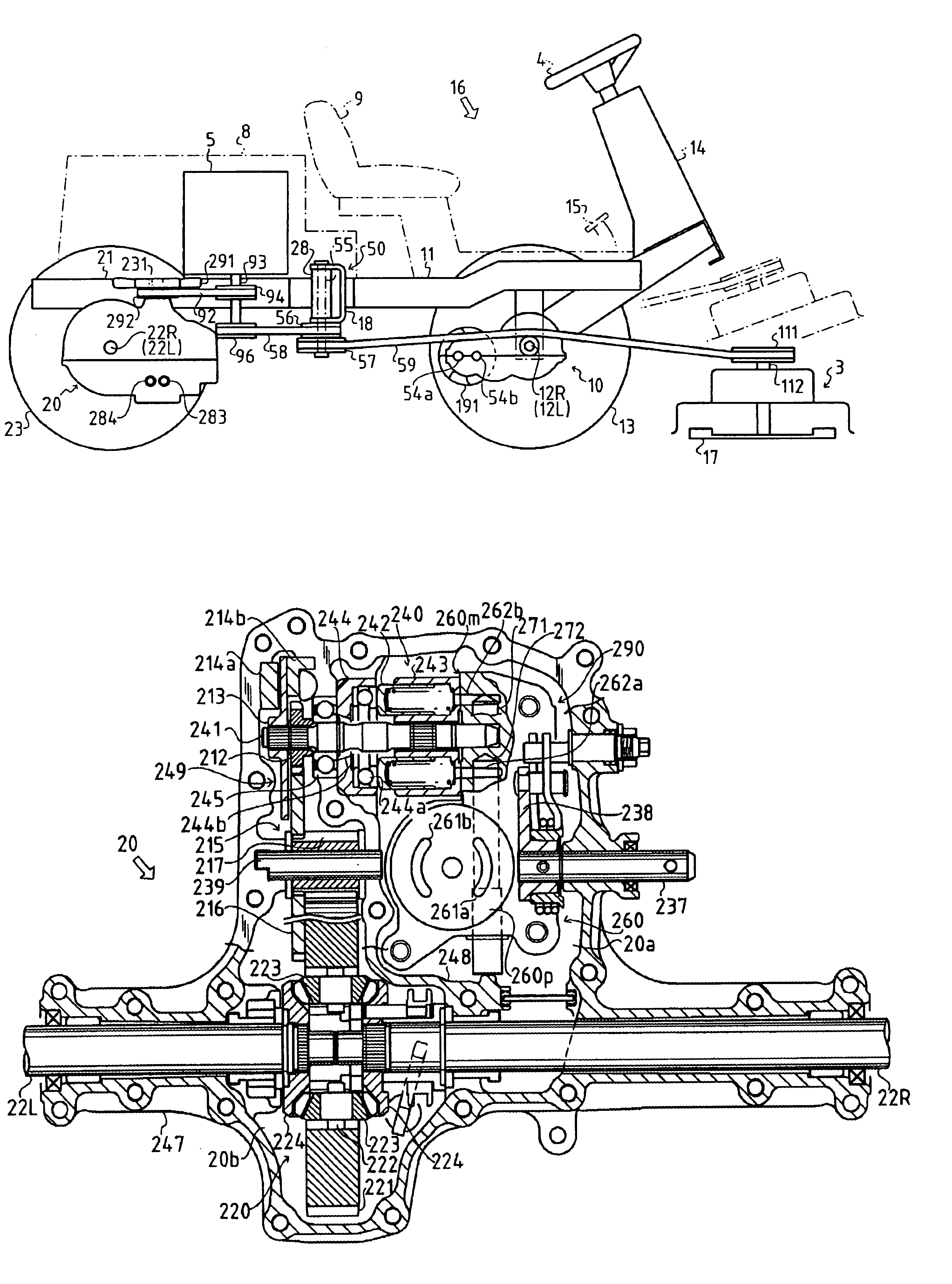
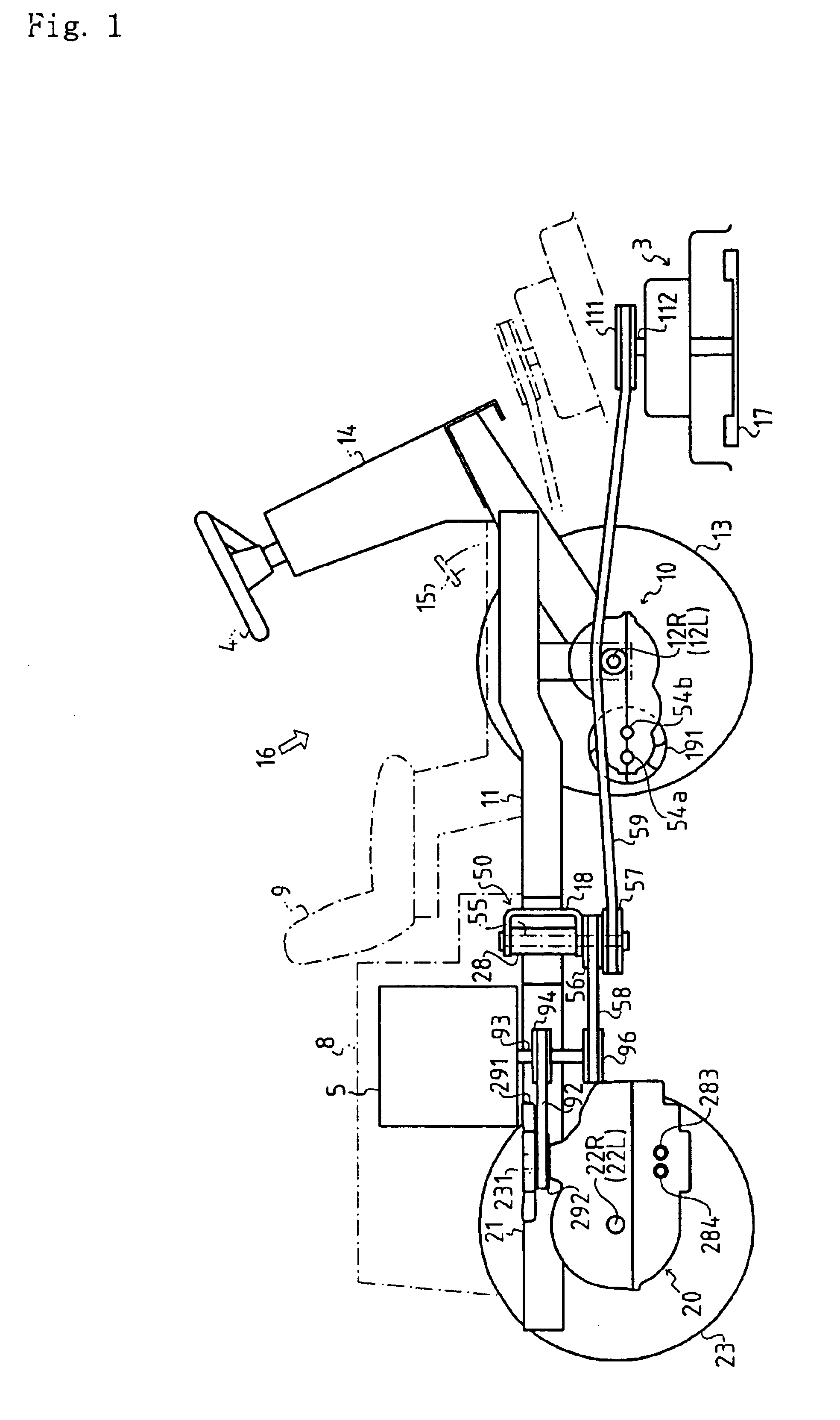
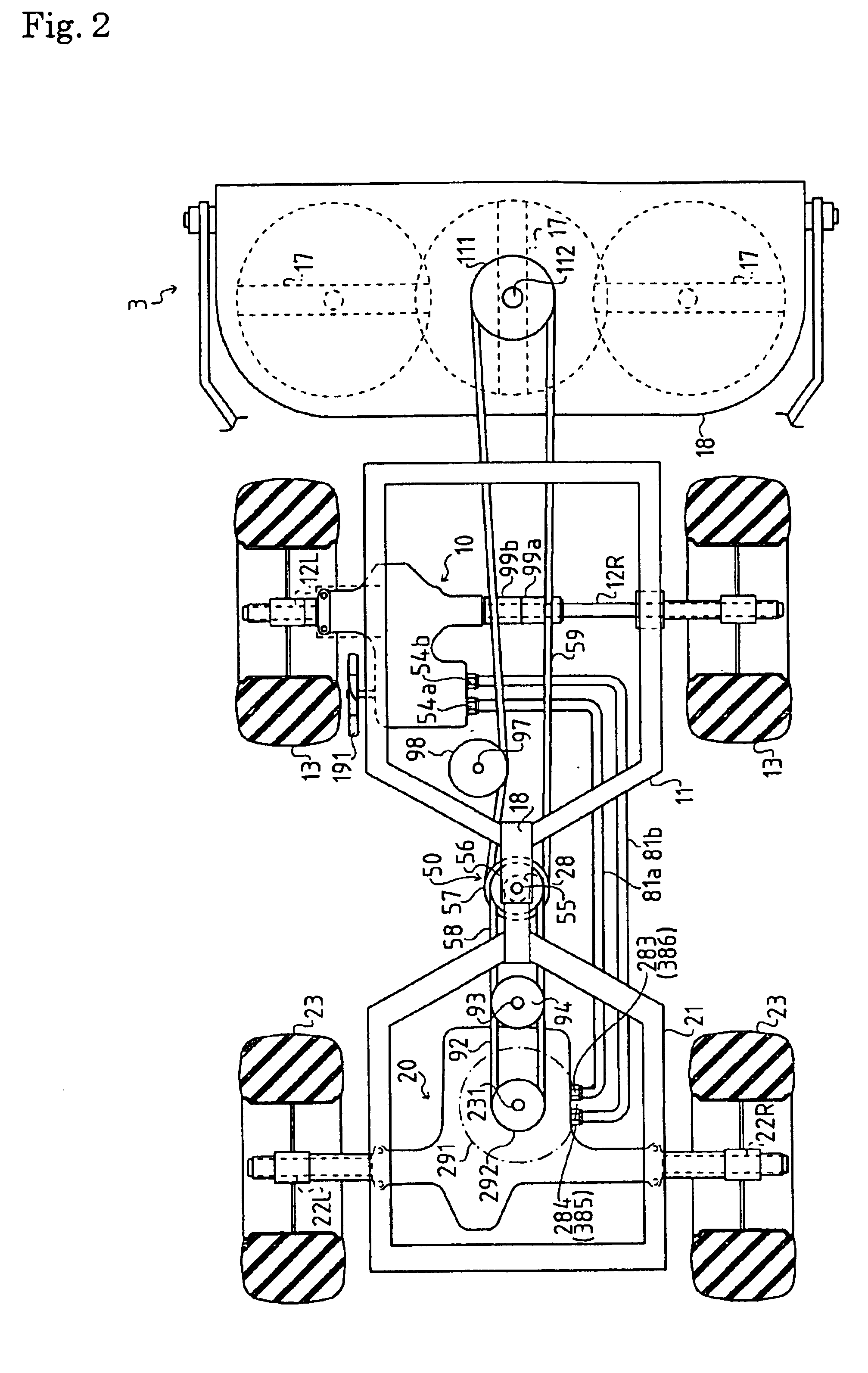
As mentioned above in the hydraulic circuit structure hydraulic motors 40 and 240, which are arranged in front and rear transaxle apparatuses 10 and 20, respectively, are fluidly connected in series to hydraulic pump 230. This in series connection form is suitable for an articulated vehicle in which coupling part 50 serves as a turning center of the vehicle and is arranged at an equidistant position from both the front and rear axles of the vehicle.

In this way, in front transaxle apparatus 10 and rear transaxle apparatus 20 are driven front wheel axles 12L and 12R and rear wheel axles 22L and 22R, respectively, thereby realizing a four-wheel-drive vehicle which is excellent in both steering performance and running performance over bad ground conditions.

Especially, a four-wheel-drive working vehicle provided with the in series hydraulic connection has the capability of freeing its running wheels from mud. For example, even if the vehicle travels in a swamp and a front wheel is stuck...

second embodiment

Description will now be given of a hydraulic circuit structure wherein hydraulic motor 40 in front transaxle apparatus 10 and hydraulic motor 240 in rear transaxle apparatus 20 are fluidly connected in parallel to hydraulic pump 230.

As shown in FIG. 14, in a horizontal portion of a center section 360 are bored a first kidney-port 361a and a second kidney-port 361b opposite to each other. These kidney-ports 361a and 361b are open at a position where openings of the cylinder bores of cylinder block 233 pass.

On the other hand, as shown in FIG. 17, in the vertical portion of the center section 360 are bored a first kidney-port 362a and a second kidney-port 362b opposite to each other. These kidney-ports 362a and 362b are open at a position where openings of the cylinder bores of cylinder block 243 pass.

As shown in FIGS. 15, 16, and 18, in the center section are bored an upper first fluid passage 371 and a lower second fluid passage 372 parallel to each other in the longitudinal directi...


PUM


Abstract

An articulated vehicle with a working device has a first frame having a prime mover mounted thereon and supporting a first transaxle apparatus. The first transaxle apparatus includes an input shalt receiving power from the prime mover, a pair of first axles, and a hydrostatic transmission. The hydrostatic transmission comprises a variable hydraulic pump, a first hydraulic motor fluidly connected to the hydraulic pump via a fluid passage, and a housing with a port fluidly connected to the fluid passage. The second transaxle apparatus includes a pair of second axles having different lengths and a second hydraulic motor. The second hydraulic motor is fluidly connected to the port. Proximal ends of the first and second frames with respect to the vehicle are coupled to each other so that the first and second flames are rotatable around a vertical axis relative to each other when steered.

Description

BACKGROUND OF THE INVENTION1. Field of the InventionThe invention relates to a transaxle apparatus having a housing which incorporates a hydrostatic transmission (HST) and a hydraulic actuator arranged outside the housing which can be supplied with hydraulic fluid from the HST. Furthermore, the invention relates to a four-wheel-drive vehicle having first axles, which axles are supported by the housing driven by the HST, and disposed at one of front and rear positions of the vehicle, and second axles, which axles are driven by a hydraulic motor serving as the hydraulic actuator and disposed outside of the housing and the other of front and rear portions of the vehicle. More particularly, the invention relates to a four-wheel-drive articulated working vehicle.2. Related ArtA well-known articulated riding lawn mower has first and second frames which are mutually pivotally coupled at proximal ends thereof so as to turn relatively to each other around a vertically axial pivot steering op...

Claims


Application Information

Patent Timeline
IPC IPC(8): B60K7/00B60K17/10B60K17/356B60K17/34B62D12/00B62D11/18B62D11/06
CPCB60K7/0015B60K17/105B60K17/356B62D12/00B62D11/183B60K17/043B60K2001/001B60K2007/0061B60L2220/46B60Y2200/223B60K2007/0046
Inventor OHASHI, RYOTAOKADA, HIDEAKI
Owner KANZAKI KOKYUKOKI MFG
Why Eureka
Try Eureka