Spinal fluid collection system

a technology of spinal fluid and collection system, which is applied in the field of spinal fluid collection system, can solve the problems of significant risk to the patient, uncomfortable procedure, and particularly uncomfortable procedure, and achieve the effect of reducing the risk of surgery and patient discomfor

Inactive Publication Date: 2005-01-25
BUTLER BRADLEY S +1
View PDF10 Cites 6 Cited by
  • Summary
  • Abstract
  • Description
  • Claims
  • Application Information

AI Technical Summary

Benefits of technology

It is a primary object and feature of the present invention to provide a cerebrospinal fluid collection system which allows a physician to better prepare for a spinal tap procedure, reduce the time necessary to carry out a spinal tap procedure, and reduce the risk of injury and severe side affects related to spinal tap procedures. It is a further object and feature of this invention to provide a test tube rack which is not too bulky, too difficult to hold, and / or too unwieldy to be used to hold test tubes while CSF is being collected. It is a further object and feature of the present invention to provide a test tube rack which is inexpensive to manufacture, disposable, sterilizable, see-through and lightweight. Other objects and features of this invention will be shown by the following descriptions and claims.

Problems solved by technology

This procedure is very uncomfortable for the patient.
The procedure is especially uncomfortable if the patient is very young or very sick, which is often the case.
This procedure also represents significant risk to the patient.
Patients may develop severe side effects from the loss of too much CSF, including severe headaches.
The risk of the patient moving and causing injury exists for the duration of the procedure.
These risks include a risk of lacerating a spinal nerve, lacerating the meninges (causing permanent or persistent leaks of CSF), or bleeding, which complicates the interpretation of laboratory results.
These risks are increased in very young patients who are more likely to move during the procedure.
In addition, there is a risk of respiratory arrest in neonates who are held in a curled-up position for the duration of the procedure.

Method used


Image

  • Spinal fluid collection system
  • Spinal fluid collection system
  • Spinal fluid collection system

Examples


Embodiment Construction

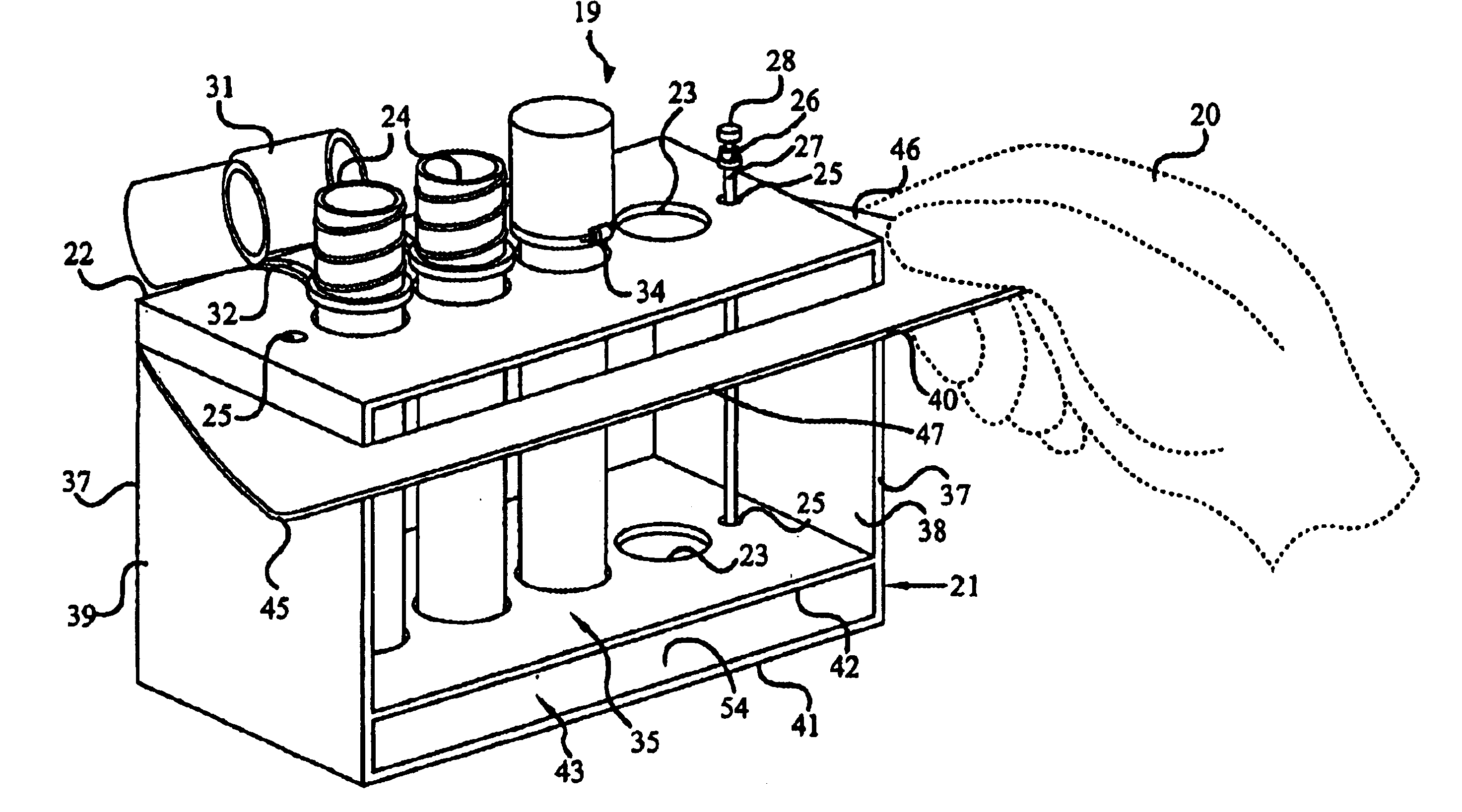
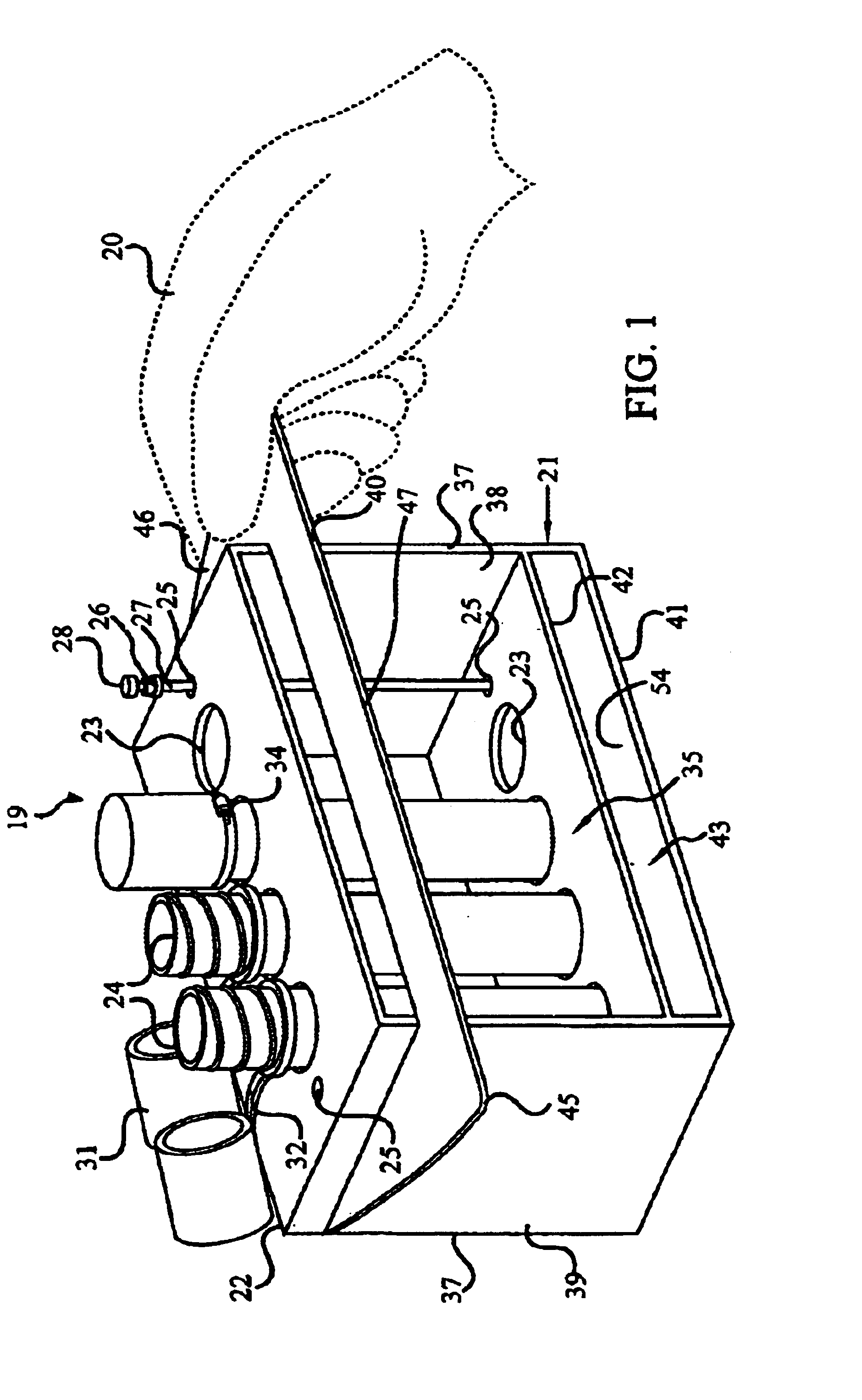
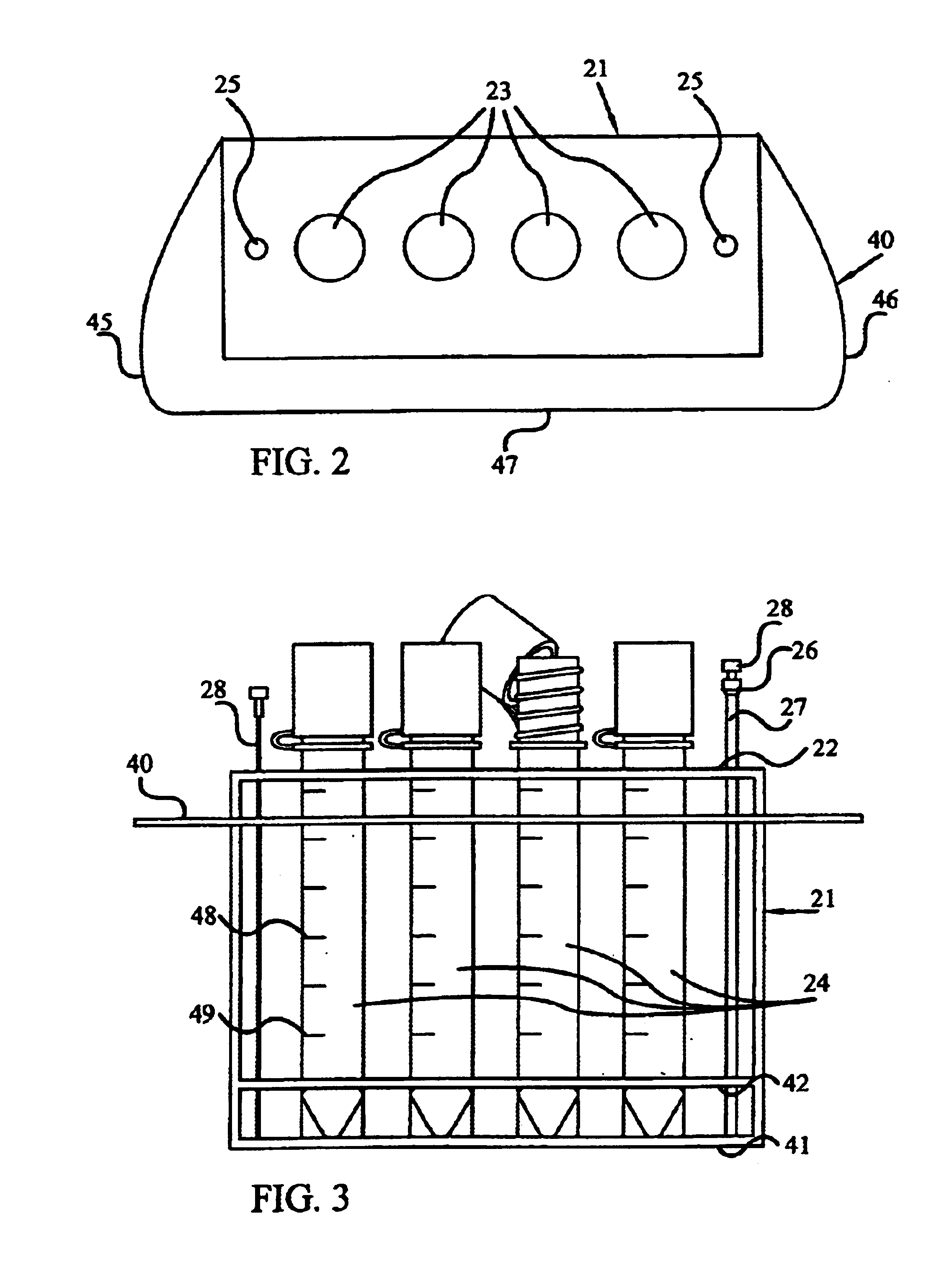
FIG. 1 is a perspective view of a preferred embodiment of the present invention illustrating a hand 20 holding the system 19, which embodies herein a spinal fluid collection system for use by a medical professional for collecting, from a spinal tap into a plurality of CSF tubes, multiple samples of cerebrospinal fluid from a patient. Illustrated in FIG. 1 is a preferred embodiment of the test tube rack 21, embodying herein a holder structured and arranged to stably hold such CSF tubes when such holder is in an upright position. The test tube rack 21 is preferably made of clear (i.e. see-through), lightweight, sterilizable, disposable, medical-grade plastic material. The test tube rack 21 has a top shelf 22, a handle shelf 40, a bottom shelf 41, an inside shelf 42, two side panels 37, and two open sides 35.

Top shelf 22 preferably has four test tube holes 23 arranged in a row across top shelf 22. These test tube holes 23 are preferably just slightly larger than the outside diameter of...


PUM


Abstract

A cerebrospinal fluid collection system and method for conveniently and safely holding in a test tube rack, during a spinal tap and collection procedure, sterile test tubes and spinal needles, needle sleeves and stylettes. A test tube rack has four holes for holding four sterile test tubes, two needle holes for holding a spinal needle, stylette or needle sleeve, and a handle for the physician to hold when moving the test tube rack during the CSF procedure. The handle can be held on the left side by a left hand, on the right side by a right hand, or in the front by either hand. The test tube rack also allows the physician to see when the appropriate amount of cerebrospinal fluid has been collected in each test tube, while such test tube is being held in the test tube rack. The test tube rack may be prepackaged with the other needed items in a sterile package.

Description

BACKGROUNDA spinal tap is a procedure which takes samples of a patient's cerebrospinal fluid (CSF). Spinal taps are performed when the physician suspects that the patient may have bleeding (such as subarachnoid hemorrhage) or an infection of the central nervous system (such as meningitis or encephalitis). These procedures are often performed in the emergency room but are also performed in a doctor's office or in a hospital setting.Usually, before beginning a spinal tap procedure, the physician, or another medical professional arranges the contents of a spinal tap “kit” on a tray, positioned next to where the physician will be sitting to perform the procedure. The “kit” usually consists of four sterile tubes, a spinal needle (with a stylet inserted through the spinal needle), along with items for sterilizing the patient's skin and draping the patient. Sometimes a test tube rack to hold the tubes is also positioned on the tray. Before the procedure, the physician or another medical pr...

Claims


Application Information

Patent Timeline
Patent Type & Authority Patents(United States)
IPC IPC(8): B01L9/00B01L9/06
CPCB01L9/06
Inventor BUTLER, BRADLEY S.EGAN, MICHAEL T.
Owner BUTLER BRADLEY S
Why Eureka
Try Eureka