Detection of loss of cooling air to traction motors

a technology of traction motors and detection methods, applied in the direction of motor/generator/converter stoppers, motor/generator/converter control, emergency protective arrangements responsive to undesired changes, etc., can solve the problem that the algorithm cannot take this condition into account, the assumption of valid assumptions may not be valid, and the speed of the blower can be increased. , the effect of reducing the motor speed

Inactive Publication Date: 2005-01-25
WESTINGHOUSE AIR BRAKE TECH CORP
View PDF23 Cites 17 Cited by
  • Summary
  • Abstract
  • Description
  • Claims
  • Application Information

AI Technical Summary

Benefits of technology

The present invention offers an improved apparatus and method for detecting an overheating condition on the traction motors. A motor thermal protection algorithm calculates the expected or predicted motor temperature based on the assumption that the blower is running at the commanded speed and that cooling air is flowing to the traction motors. The algorithm uses the expected cooling air flow rates based on the commanded blower speed and further measures the ambient air temperature and pressure to predict the motor temperature. If the predicted traction motor temperature exceeds a predetermined limit, the blower speed can be increased to supply more cooling air, the motor speed can be reduced, or the motor can be shut down. In certain circumstances the algorithmic assumptions may not be valid due to a failure in the blower system, such as a blower motor failure or a leak in the flexible hose duct through which cooling air is directed to the traction motors. For example, after the completion of maintenance work on the vehicle, maintenance personnel may forget to reconnect the cooling system duct and therefore no cooling air will be supplied to a traction motor. But because the motor protection algorithm does not measure cooling air flow, the algorithm cannot take this condition into account. As a result, the lack of cooling air flow is not detected and the motors may overheat.
Further to the present invention, the motor temperature is est

Problems solved by technology

In certain circumstances the algorithmic assumptions may not be valid due to a failure in the blower system, such as a blower motor failure or a leak in the flexible hose duct through which cooling air is directed to the traction motors.
For example, after the completion of maintenance work on the vehicle, maintenance personnel m

Method used


Image

  • Detection of loss of cooling air to traction motors
  • Detection of loss of cooling air to traction motors
  • Detection of loss of cooling air to traction motors

Examples


Embodiment Construction

Before describing in detail the particular method and apparatus for detecting the loss of cooling air flow to a traction motor in accordance with the present invention, it should be observed that the present invention resides primarily in a novel combination of steps and hardware related to detecting the loss of cooling air flow on a traction motor. Accordingly, the hardware components and method steps have been represented by conventional elements in the drawings, showing only those specific details that are pertinent to the present invention so as not to obscure the disclosure with structural details that will be readily apparent to those skilled in the art having the benefit of the description herein.

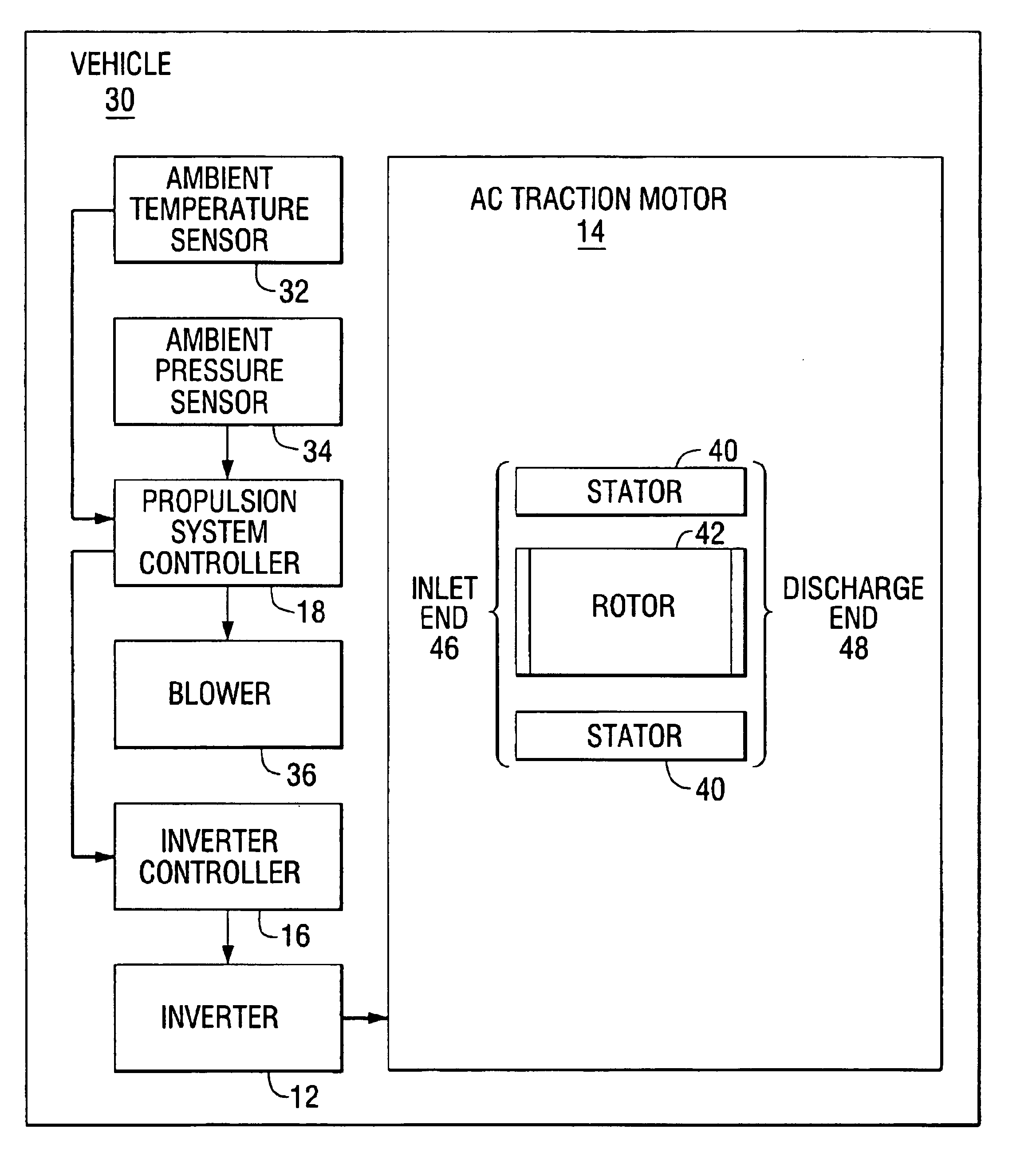
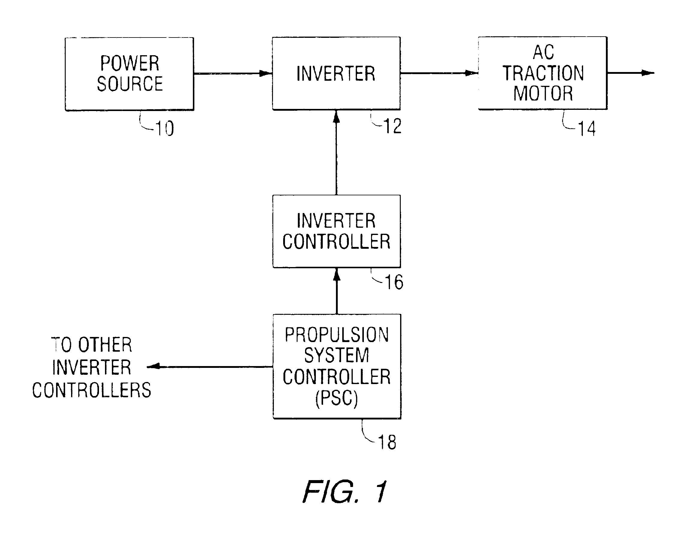
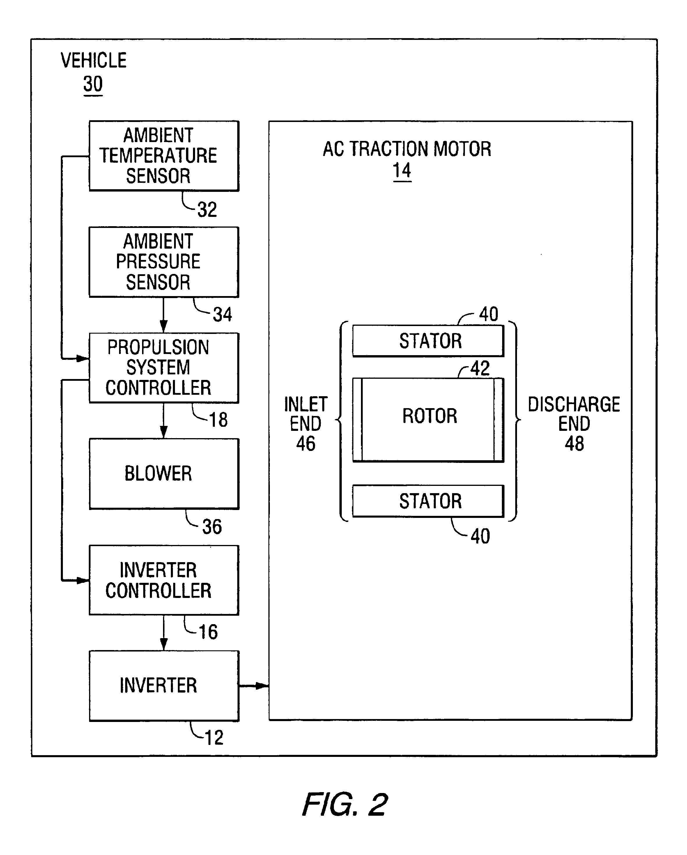
FIG. 1 is a block diagram depicting elements of a vehicle AC propulsion system. A vehicle power source 10 comprises a power source including for example, a diesel engine with a traction alternator, a battery or a wayside power source such a third rail or a high voltage catenary. Gene...


PUM


Abstract

A thermal protection apparatus for an AC traction motor including a stator, a rotor, a blower fan and an inverter includes a method and apparatus for predicting the motor temperature assuming that the blower is operational. The method and apparatus also determines an estimated motor temperature by measuring the motor resistance or the rotor slip. The estimated motor temperatures compared to the predicted motor temperature to determine the condition of the motor cooling system.

Description

The disclosure of this patent document contains material that is subject to copyright protection. The copyright owner has no objection to the copying by anyone of the patent document or the patent disclosure as it appears in the Patent and Trademark Office patent files or records, but otherwise reserves all copyrights whatsoever.BACKGROUND OF THE INVENTIONThe present invention is directed in general to an apparatus and method for detecting the loss of cooling air to traction motors, and more specifically to an apparatus and method comparing the predicted motor temperature (assuming a proper supply of cooling air to the traction motors) and the estimated motor temperature (as determined by certain temperature estimation processes since there are no temperature sensors on the motors) to determine whether cooling air is being supplied to the traction motors.Alternating current (AC) traction motors are conventionally used in conjunction with electronic inverter drives to provide propuls...

Claims


Application Information

Patent Timeline
IPC IPC(8): H02H7/085H02H6/00
CPCH02H7/0852H02H6/005
Inventor KUMAR, AJITH KUTTANNAIR
Owner WESTINGHOUSE AIR BRAKE TECH CORP
Why Eureka
Try Eureka