Seamed sleeved blanket and method for making and using same

a technology of sleeve blankets and sleeves, applied in the field of sleeve blankets and methods for making and using same, can solve the problems of slowing down the production rate, uneven and overbuilt compressible layers, and requiring grinding to the required dimensions, so as to avoid registration and print length issues, and negligible effect of print length and gap boun

Inactive Publication Date: 2005-02-01
MLP US
View PDF13 Cites 12 Cited by
  • Summary
  • Abstract
  • Description
  • Claims
  • Application Information

AI Technical Summary

Benefits of technology

This invention utilizes a pre,made or pre-manufactured, unitary flat offset printing blanket made by any of the methods known to the art of flat offset printing blanket manufacturing to produce, in mass, a unitized composite blanket covering which can be applied, in a seamed fashion, to a continuous supporting sleeve, such that the seam has a negligible effect on print length and gap bounce. The pre-made blanket material will contain requisite reinforcements which are generally layed out in a rectangular manner, and are not spiral wound. The seam is preferably parallel to the longitudinal axis of the sleeve and not skewed ideally by more than {fraction (1/16)} ″of inch for a plate of {fraction (1/16)} ″of inch plate gap to avoid registration and print length issue...

Problems solved by technology

The long evaporation time tends to slow down the production rate.
The resulting compressible layer is very rough, uneven and overbuilt, requiring grinding to the required dimensions.
The polymeric material applied by this method tends to maintain its form around the diameter of the thread resulting in unfilled valleys between this layer and the coated sleeve.
This unfilled area leads to gauge loss (thickness or diameter loss of a finished blanket sleeve—which can result in loss of printing contact) in the finished product and is sometime...

Method used


Image

  • Seamed sleeved blanket and method for making and using same
  • Seamed sleeved blanket and method for making and using same
  • Seamed sleeved blanket and method for making and using same

Examples


Embodiment Construction

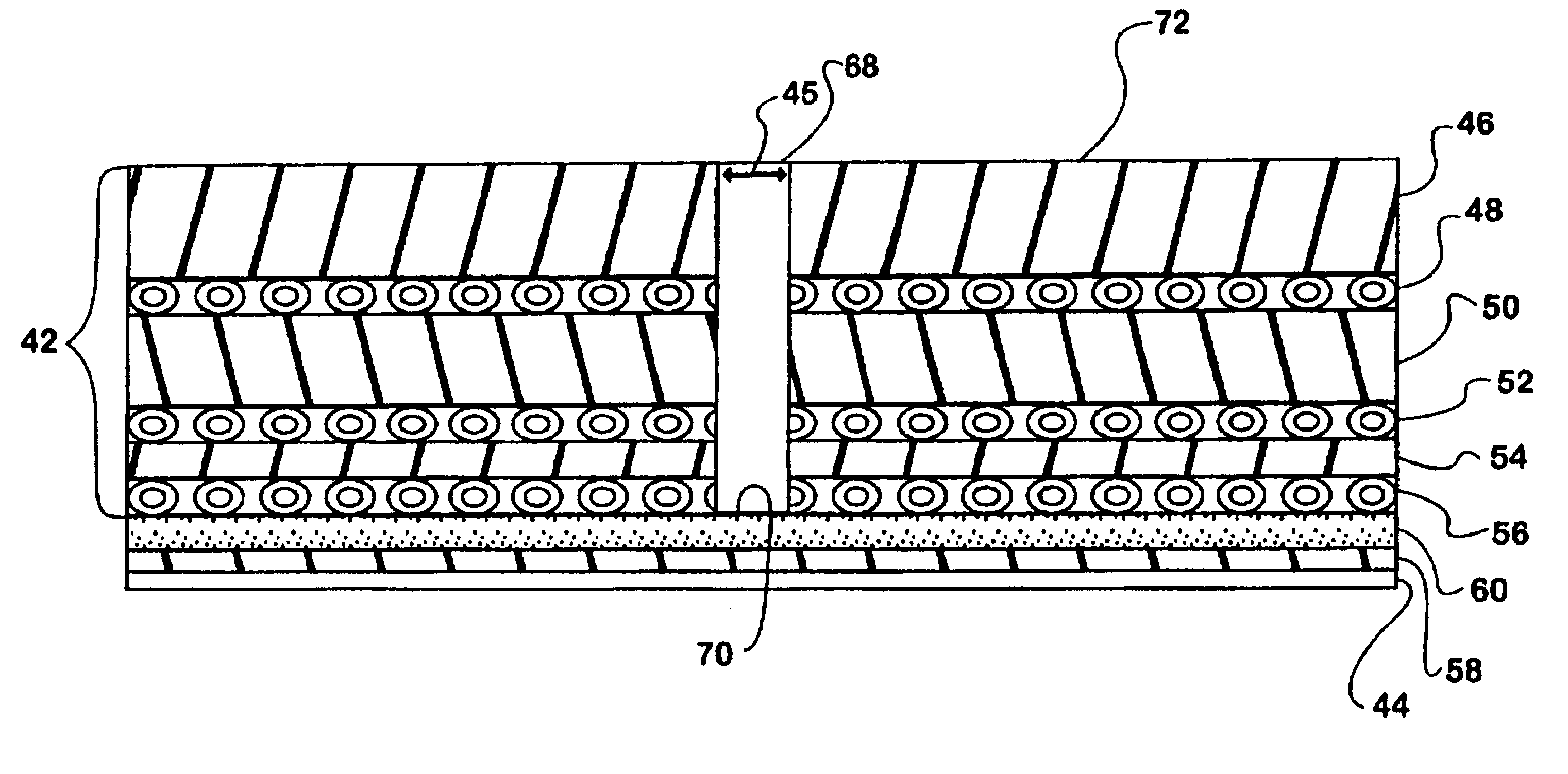
A schematic drawing of the seamed sleeved blanket 40 produced according to this invention can be seen in FIGS. 4 through 7. As shown in FIG. 6, according to this invention a conventional, flat offset printing blanket material 42 may be manufactured by methods well known to the art or purchased in roll form and cut to specific dimensions so that it can be wrapped (as indicated by the large arrows) as a solid sheet around a continuous supporting sleeve 44 to produce the seamed sleeved blanket 40 of the present invention and shown in FIG. 4, the gap or sewn being given numeral 45. Referring to FIG. 5, preferably the following construction method can be used. The blanket material 42 could be of any desired commercially available structure and could have a rubber surface 46, say 0.023 inches thick over a first outer fabric layer 48 (reinforcement), say 0.009 inches thick, over a compressible layer 50, say 0.014 inches thick, over a middle fabric layer 52 (reinforcement), say 0.011 inches...


PUM


Abstract

A gapped or seamed cylindrical offset printing blanket having pre-made blanket material mounted on a cylindrical sleeve, and a method for making same, are disclosed, wherein conventional, manufactured blanket material in flat form made by methods known in the art is adhered to a cylindrical sleeve to economically produce a blanket. The leading and trailing ends of the flat blanket material are joined in close proximity such that a small gap is formed. A seam may be made with a filler material that fills the remaining gap resulting in a seamed sleeved blanket. In use, the seam is aligned with non-print area on the adjacent printing plate, or the adjacent plate cylinder gap of the printing press. Being narrower than the plate cylinder gap, no loss of print length results from the seam.

Description

BACKGROUND OF THE INVENTIONPrior art seamless cylindrical or sleeved offset printing blanket technology is well known in the industry and documented in several patents, for example, those assigned to Heidelberg Harris (U.S. Pat. Nos. 5,323,702; 5,429,048; 5,440,981; 5,553,541; 5,535,674 and 5,654,100) and to Reeves Brothers Inc. (U.S. Pat. No. 5,522,315) the contents of all of which patents are hereby incorporated by reference. Two examples of the prior art seamless sleeved blanket 10 are illustrated in the schematic drawings of FIGS. 1 to 3. FIGS. 2 and 3 are taken in sections parallel to the circular end of the roll. For ease of illustration, the curvature of the roll has not been shown. The FIG. 2 version 10A contains two windings of spiral wound thread 12A and is typical of blankets produced by Reeves and Day (for the Heidelberg presses). The 10A version also has a sleeve 14A, usually of nickel, the spiral wrapped threads 12A, a compressible layer 16A made of typically a rubber ...

Claims


Application Information

Patent Timeline
IPC IPC(8): B41F13/08B41F13/193B41N10/00B41N10/04B41N10/06B41N10/02B41F7/02
CPCB41F13/193B41F27/1293B41F30/04B41N10/04B41N6/00Y10S428/909B41N10/06B41F13/08
Inventor BYERS, JOSEPH L.HIX, LESLIE SCOTTBADOWSKI, TIMOTHY F.STOCK, MICHAEL F.
Owner MLP US
Why Eureka
Try Eureka