Laser scanning microscope with AOTF

a laser scanning microscope and scanning image technology, applied in the field of laser scanning microscope with aotf, can solve the problems of intensity loss, possible intensity modulation in the scanned image, and the high dependence of the transmission characteristics of the acousto-optic unit on temperatur

Inactive Publication Date: 2005-02-01
CARL ZEISS MICROSCOPY GMBH
View PDF17 Cites 17 Cited by
  • Summary
  • Abstract
  • Description
  • Claims
  • Application Information

AI Technical Summary

Benefits of technology

The temperature deviation can also be compensated by an increase in intensity which compensates for the efficiency loss of the AOTF.

Problems solved by technology

The use of acousto-optics for line selection and attenuation of laser lines in a modular construction has the disadvantage that the transmission characteristics of the acousto-optic unit is highly dependent on temperature.
This leads to intensity losses and to possible intensity modulations in the scanned image.
An acceptable performance of the laser scanning microscope can only be ensured when the temperature fluctuations can be limited to + / −1° C. However, this is hardly possible in practice due to the many and various possible uses of the laser scanning microscope.

Method used


Image

  • Laser scanning microscope with AOTF
  • Laser scanning microscope with AOTF
  • Laser scanning microscope with AOTF

Examples


Embodiment Construction

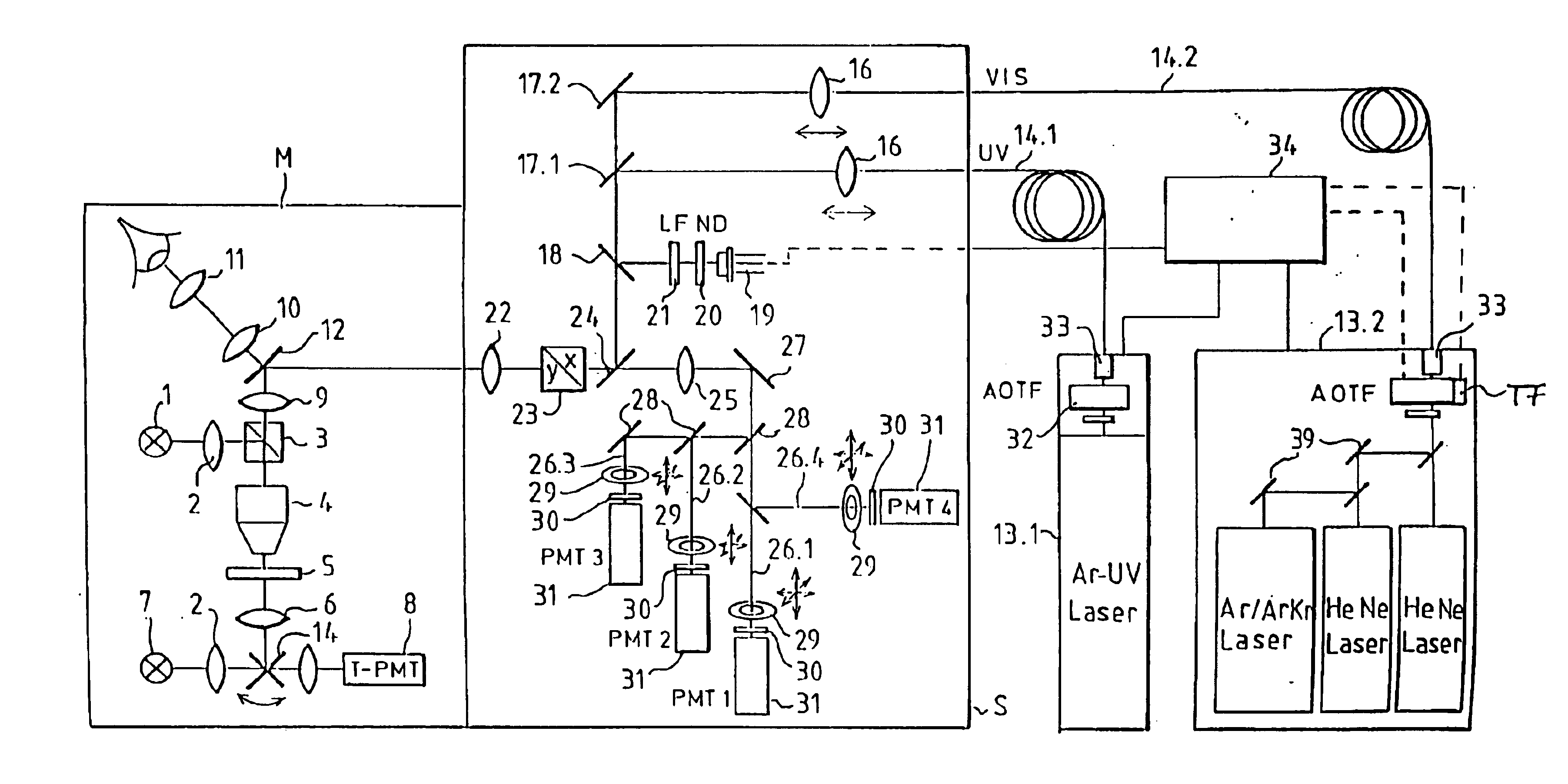
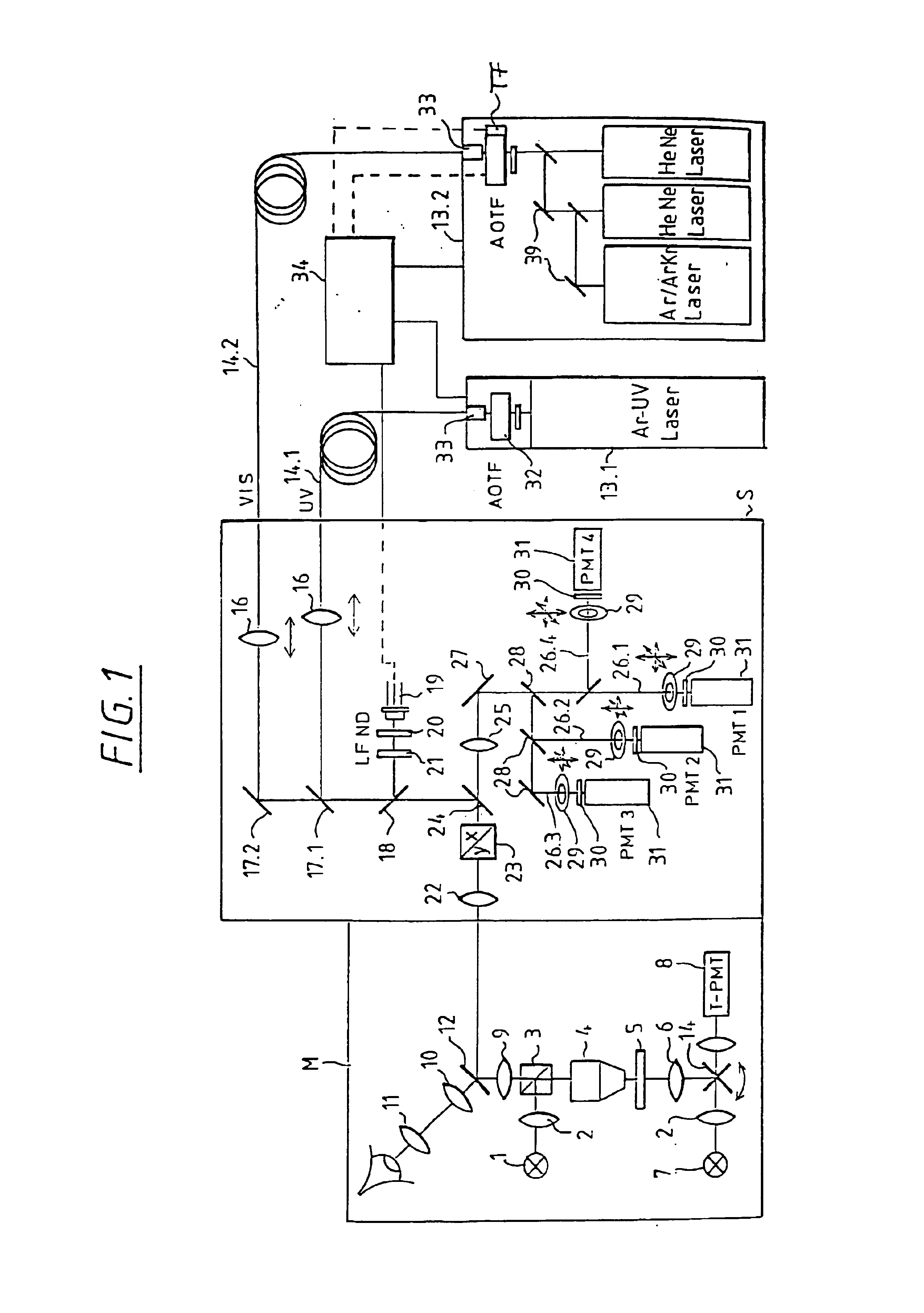
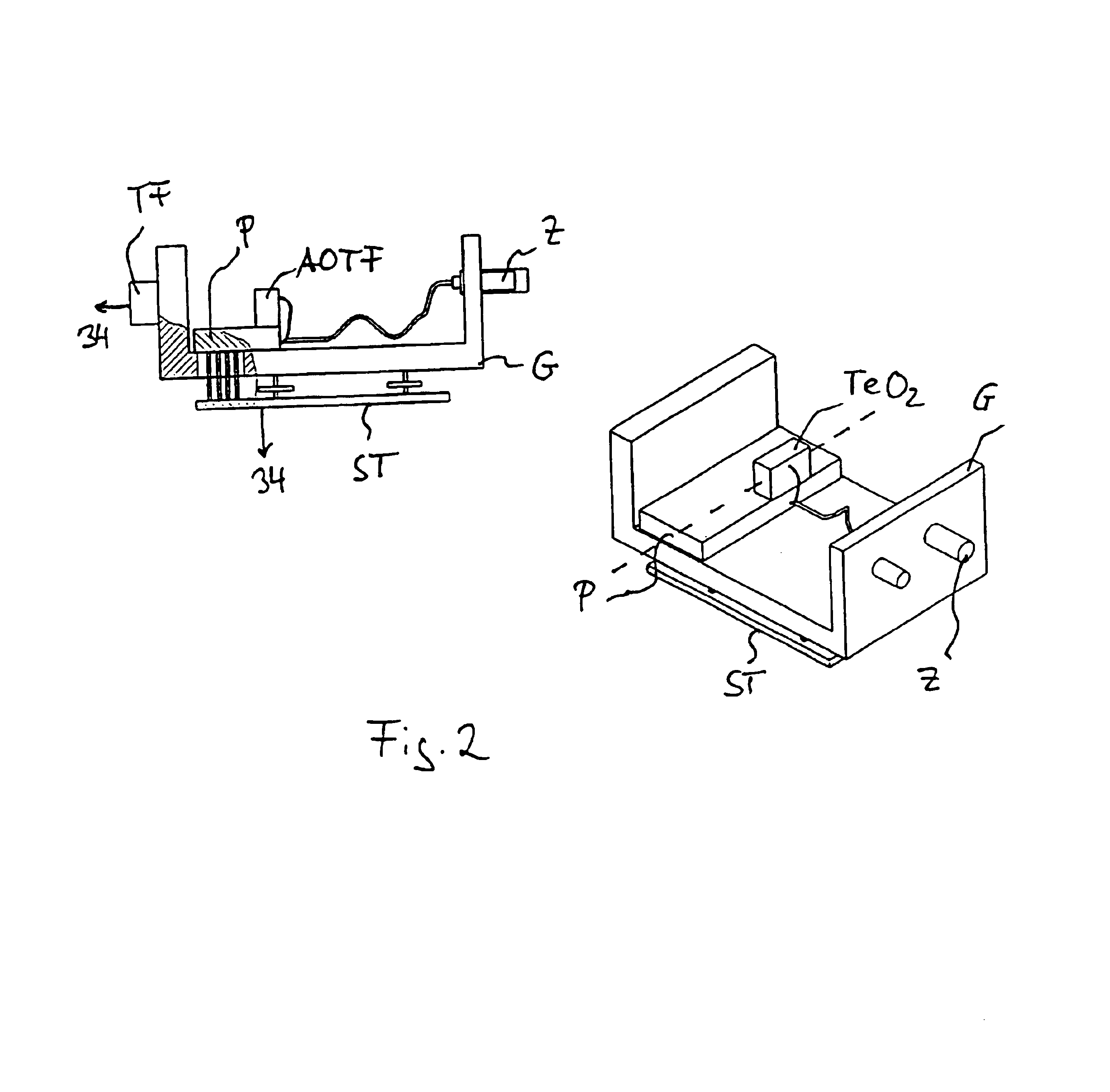
FIG. 1 shows schematically a microscope unit M and a scan head S which have a shared optical interface via an intermediate imaging Z according to FIG. 2.

The scan head S can be at the phototube of an upright microscope and also at a side output of an inverse microscope.

FIG. 1 shows a microscope beam path which is switchable between incident light scanning and transmitted-light scanning by means of a swivelable mirror 14 and comprising light source 1, illumination optics 2, beam splitter 3, objective 4, specimen 5, condenser 5, light source 7, receiver arrangement 8, a first tube lens 9, an observation beam path with a second tube lens 10 and eyepiece 11, and a beam splitter for coupling in the scanning beam.

A laser module 13.1, 13.2 receives the laser and is connected with the laser input-coupling unit of the scan head S via monomode light-conducting fibers 14.1, 14.2.

Coupling into the light-conducting fibers 14.1, 14.2 is carried out by means of displaceable collimating optics 16 wh...


PUM

PropertyMeasurementUnit
temperatureaaaaaaaaaa

Abstract

A laser scanning microscope with an AOTF in the laser input-coupling beam comprises a temperature gauge provided in the environment of the AOTF or in the vicinity thereof or connected therewith. A laser scanning microscope with an AOTF in the laser input-coupling beam path comprises that the AOTF and/or its environment are/is heated or cooled.

Description

BACKGROUND OF THE INVENTIONa) Field of the InventionThe invention relates to a laser scanning microscope with AOTF.b) Description of the Related ArtIt is already known to combine lasers of different wavelengths in a laser scanning microscope by means of a beam splitter and to couple the lasers into a light-conducting fiber by means of an AOTF (acousto-optic tunable filter) with a grating which is realized by varying the refractive index and whose grating constant can be varied corresponding to its high-frequency driving. The wavelength, which is diffracted in the first order by the AOTF, and the intensity are adjusted by controlling the AOTF; the intensity is adjusted by the amplitude of the sound wave and the wavelength is adjusted by the frequency of the sound wave.The use of acousto-optics for line selection and attenuation of laser lines in a modular construction has the disadvantage that the transmission characteristics of the acousto-optic unit is highly dependent on temperatu...

Claims


Application Information

Patent Timeline
Patent Type & Authority Patents(United States)
IPC IPC(8): G02B21/00G01K11/22G01B11/00G01N21/27
CPCG02B21/002
Inventor SIMON, ULRICHWILHELM, STEFAN
Owner CARL ZEISS MICROSCOPY GMBH
Why Eureka
Try Eureka